User Manual
146
User Manual
147
Multi-segment instruction 5
Default
:
0.0
Multi-segment instruction 6
Default
:
0.0
Multi-segment instruction 7
Default
:
0.0
Multi-segment instruction 8
Default
:
0.0
Multi-segment instruction 9
Default
:
0.0
Multi-segment instruction 10
Default
:
0.0
Multi-segment instruction 11
Default
:
0.0
Multi-segment instruction 12
Default
:
0.0
Multi-segment instruction 13
Default
:
0.0
Multi-segment instruction 14
Default
:
0.0
Multi-segment instruction 15
Default
:
0.0
PC-05
PC-06
PC-07
PC-08
PC-09
PC-10
PC-11
PC-12
PC-13
PC-14
PC-15
Multi-segment instructions can be used in three situations: as a frequency
source, as a VF-separated voltage source, as a set source for the process
PID. In three applications, the dimension of the multi-segment instruction is
relative, ranging from -100.0% to 100.0%. When used as a frequency source,
it is a percentage of the relative frequency; when the VF is separated from the
voltage source, it is relative to the rated voltage of the motor. Percentage;
since the PID given is originally a relative value, the multi-segment instruction
does not require a dimension conversion as a PID setting source.
The multi-segment instruction needs to be switched according to the
different states of the multi-function digital X. For details, please refer to the
relevant description of the P4 group.
PC-16
Simple PLC
operation mode
Default
:
0
0:Single run end shutdown
1: Keep the final value at the
end of a single run
2: Always cycle
The simple PLC function has two functions: as a frequency source or as a
voltage source for VF separation.
When the simple PLC is used as the frequency source, the positive and
negative of PC-00~PC-15 determine the running direction. If it is negative, it
means the inverter runs in the opposite direction.
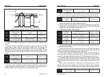
Figure 6-33 Simple PLC schematic
2 : Always cycle the inverter after completing a cycle, it will automatically
start the next cycle until it stops when there is a stop command.
As a frequency source, the PLC has three modes of operation. When the
VF is separated as a voltage source, these three modes are not available.
Among them:
0 : Single run end shutdown
After the inverter completes a single cycle, it will stop automatically and
need to give the running command again to start.
Automatically maintain the running frequency and direction of the last
segment.
1 : After the single run ends, the final value is maintained. After the inverter
completes a single cycle,
PC-17
Simple PLC
power-down
memory selection
Default
:
00
Ones place:Power-down memory
selection
0: No power loss, no memory
1: Power failure memory
Tens place: stop memory selection
0: Stop without memory
1: Stop memory
The PLC stop memory records the previous PLC running phase and
running frequency when it stops, and continues to run from the memory
phase in the next run. If you choose not to remember, the PLC process will be
restarted each time you start.
PLC power-down memory refers to the operating phase and operating
frequency of the PLC before the power-down, and continues to run from the
memory phase the next time the power is turned on. If you choose not to
remember, the PLC process will be restarted every time you power up.
Running direction
PC-19
PC-21
PC-01
PC-18 PC-20 PC-23
PC-02
PC-14
PC-15
Status signal output
250ms pulse
Time t
PC-00
......
Chapter 6
Chapter 6
0.0Hz ~ ±P0-10
0.0Hz ~ ±P0-10
0.0Hz ~ ±P0-10
0.0Hz ~ ±P0-10
0.0Hz ~ ±P0-10
0.0Hz ~ ±P0-10
0.0Hz ~ ±P0-10
0.0Hz ~ ±P0-10
0.0Hz ~ ±P0-10
0.0Hz ~ ±P0-10
0.0Hz ~ ±P0-10


