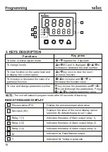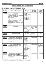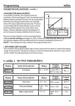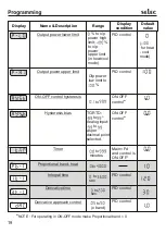
2.Terminals and electrically charged parts must not be touched when the power
is ON.
CAUTION:
6.Cable used for connection to power source, must have a cross section of 1 or
greater. These wires shall have insulation capacity made of at least 1.5KV.
WIRING INSTRUCTIONS
1.To prevent the risk of electric shock power supply to the equipment must be
kept OFF while doing the wiring arrangement.
3.Wiring shall be done strictly according to the terminal layout with shortest
connections. Confirm that all connections are correct.
4.Use lugged terminals to meet M3.5 screws.
5.To eliminate electromagnetic interference use of short wire with adequate
ratings and twists of the same in equal size shall be made.
INSTALLATION GUIDELINES
Mechanical Installation:
For installing the controller
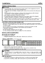
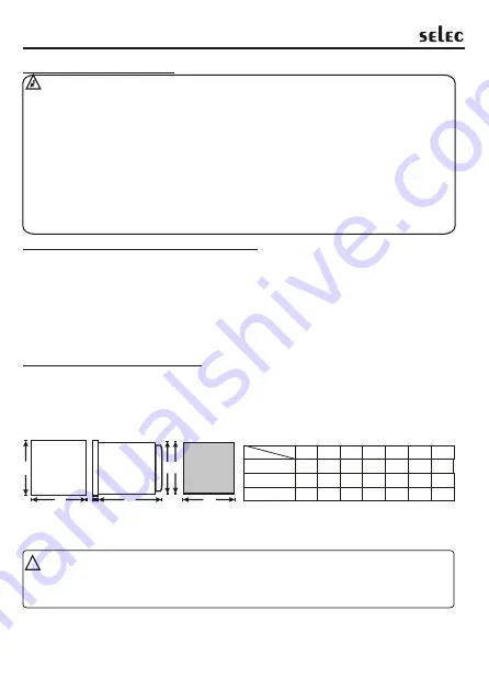
1.Prepare the panel cutout with proper dimensions as shown.
2.Remove the clamp from the controller.
3.Push the controller into the panel cutout. Secure the controller in its
place by pushing the clamp from the rear side.
CAUTION:
The equipment in its installed state must not come in close proximity to any
heating sources, caustic vapors, oils, steam, or other unwanted process by-
products.
!
8
Installation
ELECTRICAL PRECAUTIONS DURING USE
Electrical noise generated by switching of inductive loads can create momentary
disruption, erratic display, latch up, data loss or permanent damage to the instrument.
To reduce noise:
A) Use of MOV across supply of temperature controller & snubber circuits
across loads are recommended. Part numbers are as follows:
1. Snubber: APRC-01.
B) Use separate shielded wires for inputs.
C) The unit should preferably be shielded from the contactor.
2.Layout of connecting cables shall be away from any internal EMI source.
1.Use proper input power cables with shortest connections and twisted type.
EMC Guidelines:
OVERALL DIMENSIONS
(All dimensions in mm)
E
A
Panel Cutout
F
D
B
C
G
A
B
C
D
E
F
G
PID500
48
48
100
45
7
45
45
96
96
74.5
90
10
92
92
PID330
96
48
74.5
90
10
92
45
PID110
MODELS
DIM

