www.FreeStyleFlooring.com
www.StaticStop.com
©2019 SelecTech, Inc. All Right Reserved
Selec
Tech
by
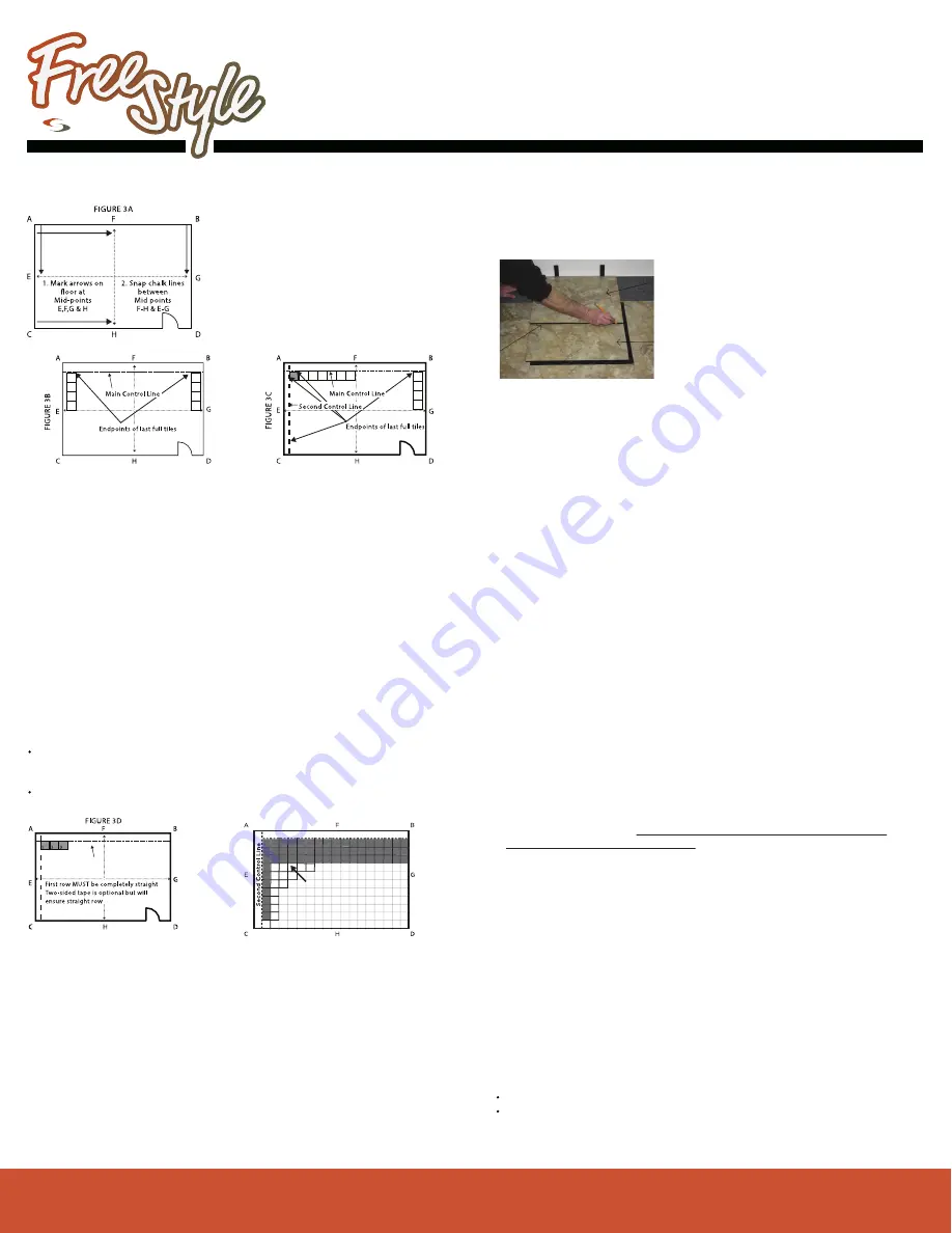
Establish Midlines and Midpoint of Room (FIGURE 3A)
• Measure from point A to B. Record that measurement and divide it by 2
• Starting at Point A, measure to find the
halfway point on wall AB.
• Mark that Midpoint with an arrow, as accu-
rately as possible. (See Point F)
• Repeat Steps 1 & 2 along wall CD.
• Snap a chalk line between these points,
shown as line FH.
• Repeat the process to find the midpoints
on wall AC and wall BD.
• Snap a chalk line between these points,
shown as line EG in Figure 2
Establish Control Lines and Starting Point (FIGURE 3B &3C)
Install The Control Row (FIGURE 3D)
• Starting at Midline EG along Wall AC lay full tiles as shown to the point
where a full tile will not fit.
• Carefully mark a the point at the Finished Edge of the last tile. Note: You
must mark that line at the Finished Edge of the tile, not at the edge of the
Interlock Extensions. (See FIGURE 1)
• You may either repeat the process, laying tiles along the opposite wall or
multiply the number of full tiles by 18.5. Measure that length from the Midline
to the wall and mark that point along the opposite wall.
• Snap a chalk line between these two points. This is the Main Control Line for
your installation.
• Repeat the process along the other walls to determine the number of full
tiles. That chalk line will be your Second Control Line.
• The corner formed where the Main and Second Control Lines meet is the
Start Point for your installation.
Complete Field Tile Installation (FIGURE 3E)
Simpler Installation
Grounding FreeStyle ESD
Care, Maintenance, and Additional Information
It is essential to keep the first row straight on the Control Line. This will keep
the installation square and ensure easy installation. Failure to do so may cause
gapped or excessively tight seams as you add rows.
Create a Template to Cut Edge Tiles
•
Create an End Cut Template by cleanly
removing the interlock extension from one tile.
•
Beginning in a corner, place a loose tile over
the installed corner tile.
•
Line up the edges precisely.
Be sure the interlocks are oriented the
same way as the installed tile.
•
Lay the End Cut Template over the loose tile
to be cut. Butt the template against the wall, placing 1/4” spacers
near the corners (you may use a “slice” of a tile to achieve a 5/16” space).
Line up the other edges and mark a line where the template meets the
loose tile.
•
Remove the marked tile and cut along the drawn line.
•
If required, gently lift the edge of the “field tile” and slide the cut tile Inter
Interlock Extension under the “field tile”. Butt tiles together and align corners.
Seat the tile corner with the heel of your hand. Use a dead blow hammer to
finish seating the edges. Check to ensure minimum expansion space
along the wall.
•
Continue using this method around the perimeter of the room until all tiles
are installed.
Settling Seams
Door Jambs
Detail Cuts
Due to the tight seam design, tiles may initially pop up during installation. For
best interlock joint seating, roll over all joints with a roller, applying pressure
to the joints as you roll across them. You may repeat this process after the
floor has had a chance to “settle in” for a few days. You may also go back over
the floor re-tapping any high points with the dead-blow hammer.
Transitions and Relief Joints
To transition to the sub-floor or to adjacent flooring install a transition piece.
SelecTech has a number of transitions and edge piece accessories available
for most situations. See FreeStyle Technical Bulletin 060114-FreeStyle
Standard Reducers and Transitions for recommended options.
Rolling Loads
For unusual conditions or extraordinary installations contact
SelecTech for guidance (877-738-4537)
Install ROW 1 carefully along the Main Control Line. Before starting ROW
2, CLOSELY check ROW 1 and adjust as needed to keep it on the Main
Control line
Install a 2nd row.
Once you have installed 2 or 3 rows assemble a number of tiles along the
Second Control Line, perpendicular to the Main Control Line. Check for
squareness of the assembled tiles. Then complete installation of the field
tiles in a “pyramid” pattern as shown in Figure 3E. This will help maintain
square during the installation. Continue to add tiles along the Second
Control Line and then fill field tiles until field tile installation is complete.
Edge cuts should not be smaller than six inches. Once you have
established your Control Lines, if you find that the distance between either
of the Control Lines to the wall is less than 6” you may want to begin with
a full tile close the wall. In this case, or if you simply prefer the simpler
installation with less cutting, follow all of the steps above.
It is recommended that a copper grounding wire be placed at least every
1,000 square feet,throughout the installation. FreeStyle Grounding kits can
be ordered from SelecTech. For additional information on grounding: visit
www.staticstop.com
For detailed care and maintenance, warranty information, grounding
instructions for ESD tiles, and other technical guidelines,
visit the tech documents page on our websites:
For Freestyle and FreeStyle Biolock visit www.freestyleflooring.com
For FreeStyle ESD, ESD Plus and Designer Series visit
www.staticstop.com
You will still establish two Control Lines but one or both of them will be
close to the wall (leaving at least a 1/8” gap between the tile edge and the
wall for expansion). In this case measure from each of the points marking
the end of the last full tile to the wall. Snap a chalk line along the wall. This
is your starting line.
Measuring, Cutting, and Laying Cut Tiles Around Perimeter
For the best finish you will need to cut the door jamb moldings so the tiles fit
freely under them. This is easily done with a “door jamb” or “undercut” saw
available at most hardware stores. Cut the jamb using a tile to establish the
proper cutting height. Note: In some cases you will also have to cut the door
bottom due to inadequate clearance. Your door should not rub anywhere on
the tile when it is open and shut.
The thickness of FreeStyle makes it difficult to cut by hand. A jigsaw is
recommended for more detailed cuts. Heating the tile with a heat gun also
makes it easier to cut.
Heavy rolling loads in commercial environments can cause the tiles to
compress and creep, and come unsnapped along traffic areas and
particularly at turning or pivot points. To prevent this apply a releasable
adhesive (Parabond M5080, or equal) in these areas only. Follow adhesive
manufacturer’s instructions for application. Alternatively, apply a grid of a
2-sided tape such as 1” Ultrastik (available from SelecTech) or equal in the
high traffic areas.
FIGURE 3E
Main Control Line
Once Main Control Line and
Second Control line tiles are
in place complete installation
in “pyramid” fashion.


