background image

M 9 6 5 2 7 1

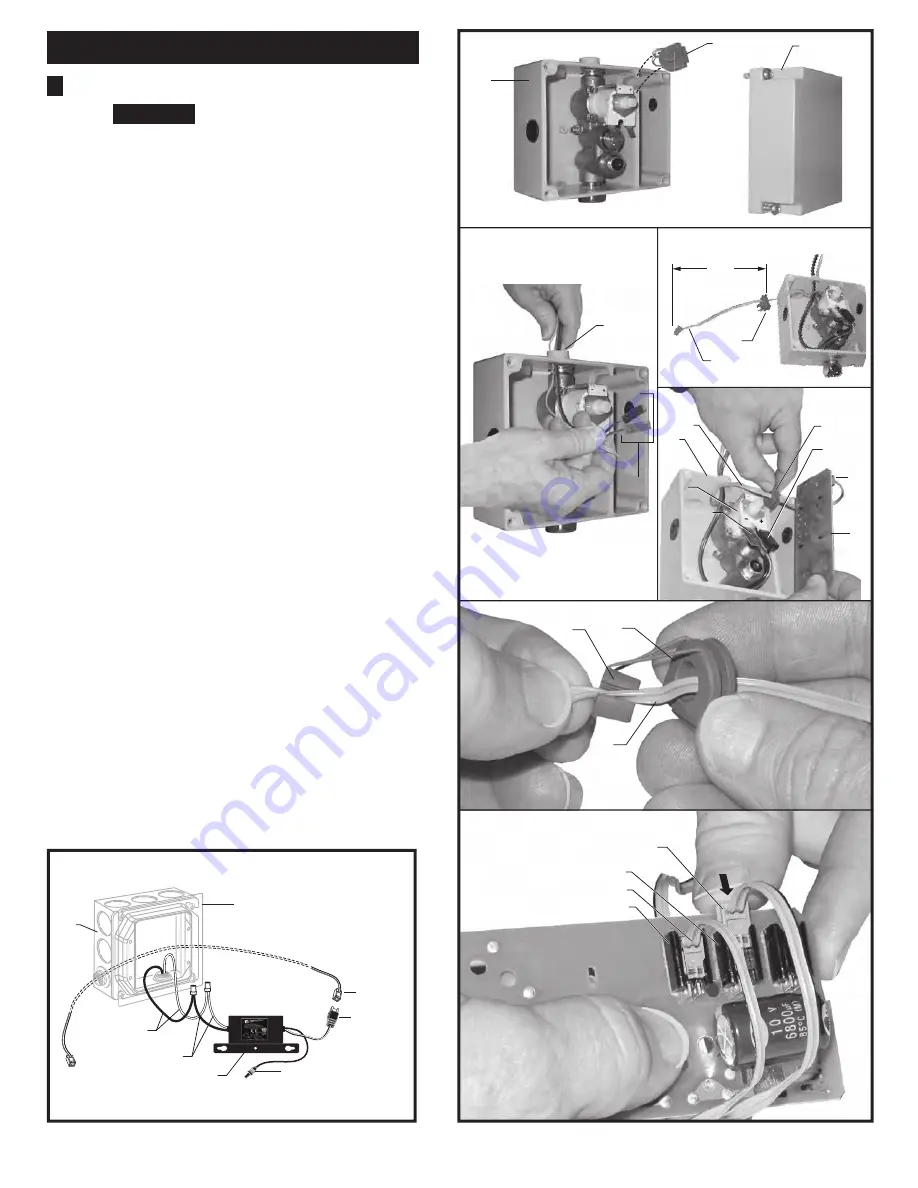
Fig. 1e

Fig. 1f

8

10

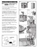
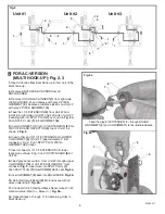
ELECTRICAL INSTALLATION

4

Fig. 1

Fig. 1b

1.

 Remove ENCLOSURE COVER 

(1)

Fig. 1.


2. 

Feed the WIRE CONNECTORS 

(2)

 through the top 

of ENCLOSURE 

(5)

Fig. 1a.

3.

 Remove GROMMET 

(4)

 from ENCLOSURE 

(5)

Fig. 1.

4.

 Feed the gray SENSOR WIRE 

(7)

  through 

GROMMET 

(4)

, 4" from CONNECTOR. 

Fig. 1b.

 Insert 

gray SENSOR WIRE 

(7)

 into SPLIT PLUG 

(9)

. Push 

SPLIT PLUG 

(9)

 into GROMMET 

(4)

 to seal. 

Fig. 1d.

5.

 Insert GROMMET 

(4)

 back into ENCLOSURE 

(5)

Fig. 1c.

6.

 Install CIRCUIT BOARD 

(3)

 into ENCLOSURE 

(5)


with SENSOR WIRE 

(7)

 under BOARD. 

Fig. 1c.

7.

 Insert SENSOR WIRE CONNECTOR 

(8) 

and 

EXTENSION WIRE CONNECTOR

 (11)

 into available 

CIRCUIT BOARD RECEPTORS 

(10)

 slots. 

Fig. 1e.


8.

 Connect wires from SENSOR to SOLENOID VALVE 

(6)

 (Red to +, Black to -). 

Fig. 1d.

9. 

Replace ENCLOSURE COVER 

(1)

. Tighten cover 

screws firmly. 

10.


Contractor to supply ELECTRICAL BOX (12) 

and connection to ENCLOSURE (5). 

Mount POWER 

SUPPLY 

(13)

 into ELECTRICAL BOX 

(12)

.  Connect 

White and Black power connections to POWER 
SUPPLY CABLE 

(14)

.

 Fig. 1f.

11.

 Connect the EXTENSION WIRE 

(16)

 to the 

POWER SUPPLY CABLE 

(15)

FIG. 1f.

    ELECTRICAL CONNECTIONS; Fig. 1

1

4

8

RED

6

Fig. 1c

Fig. 1d

7

4

9

1

4

7

5

4

4"

3

CAUTION

Before opening ENCLOSURE

disconnect AC power supply.

BLACK

F

5

2

Fig. 1a

5

7

10

BLACK & WHITE

POWER

CONNECTIONS

15

13

CONNECTOR NOT

USED IN THIS 

INSTALLATION

16

14

4" ELECTRICAL BOX

OR EQUIVALENT BY

OTHERS

11

12

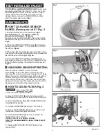
Summary of Contents for 6059.193

Page 1: ...rt amstd com For Parts Service Warranty or other Assistance please call 1 800 442 1902 In Canada 1 800 387 0369 NOTE TO INSTALLER Please give this manual to the customer after installation In Toronto Area only 1 905 3061093 M965271 Product No s Options Specifications How to Install Electrical Hook up Maintenance FAQ s Replacement Parts 1 2 2 3 4 5 6 7 8 9 6059 193 ICU Faucet shown Installed on Ame...

Page 2: ...rdered separately 10 Mixing Valve optional must be ordered separately 11 Installation Instructions 1 Selectronic Spout Assembly 2 Mounting Kit 3 Electrical Enclosure 4 Supply Hose 5 10 ft Extension Wire 6 Power Supply 7 6 5 I n s t a l l a t i o n I n s t ru c t i o n s I n s t a l l a t i o n I n s t ru c t i o n s In Toronto Area only 1 905 3061093 Certified to comply with ASME A112 18 1M 2012 A...

Page 3: ...ounting Operates on AC permanent power In line strainer for solenoid is integral Single inlet 3 8 compression built in checks and flexible stainless steel 16 1 4 reach inlet hose for spout connection Note All plumbing and electrical wiring must be installed in accordance with applicable codes regulations and standards 1 Insert WIRES 1 FLEX HOSE 2 and SPOUT SHANK 3 through center hole of mounting s...

Page 4: ...EWS 4 Tighten to secure ENCLOSURE 1 to mounting surface NOTE The illustration shows the ICU FAUCET mounted on the American Standard ICU Sink Faucet can be installed on almost any sink or countertop For Faucet installation on the American Standard ICU Sink see instruction sheet No 7301793 100 ICU Sink System supplied with Sink for more detailed information MOUNT ENCLOSURE Fig 2 2 1 Connect SUPPLY N...

Page 5: ...WIRE CONNECTOR 11 into available CIRCUIT BOARD RECEPTORS 10 slots Fig 1e 8 Connect wires from SENSOR to SOLENOID VALVE 6 Red to Black to Fig 1d 9 Replace ENCLOSURE COVER 1 Tighten cover screws firmly 10 Contractor to supply ELECTRICAL BOX 12 and connection to ENCLOSURE 5 Mount POWER SUPPLY 13 into ELECTRICAL BOX 12 Connect White and Black power connections to POWER SUPPLY CABLE 14 Fig 1f 11 Connec...

Page 6: ...Unit 2 approximately 4 from connector Fig 3 Push SPLIT PLUG 7 into GROMMET 8 to seal 7 Insert connector of 10 ft EXTENSION into lower receptor as shown in fig 3 on CIRCUIT BOARD 6 of Unit 2 8 Feed gray sensor wire 9 from Unit 2 through upper U GROMMET 10 of Unit 2 ENCLOSURE 4 from connector Fig 3 Insert wire into SPLIT PLUG 7 Push SPLIT PLUG 7 into GROMMET 8 to seal Fig 3a 9 Insert GROMMET 2 back ...

Page 7: ...G LED UP TO 10 250mm BLINKING LED 2 2 1 Remove ENCLOSURE COVER 2 Close SUPPLY STOP 5 with 4mm Hex wrench Note Keep water flowing out of faucet while shutting off 3 Pull off Red 1 and Black 2 CONNECTORS from SOLENOID VALVE 3 4 Unthread STRAINER 4 using a 7 16 socket 5 Pull out the STRAINER 4 and clean with an old toothbrush Rinse thoroughly with water 6 Install the STRAINER 4 back in its place and ...

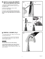
Page 8: ...r use polishing power detergent or a nylon scrub brush They will damage the surface of the spout or Sensor 5 Fig 5 7 1 Remove SET SCREW 1 with FLAT BLADE SCREWDRIVER 2 Pull off SPOUT 3 from faucet base Fig 4 4a 2 Remove HOUSING 4 and remove FLOW RESTRICTOR 5 Fig 4b 3 Rinse clean FLOW RESTRICTOR 5 Reassemble and install into SPOUT BASE 6 Reassemble SPOUT 3 onto SPOUT BASE 6 and tighten SET SCREW 1 ...

Page 9: ...ow out of faucet when I m in the sensor range A Check sensor If sensor blinks 2 times interrupted by pause replace battery or call 1800 442 1902 Q Why does the faucet operate the opposite of expected Turns On when not in sensor range but turns off when in sensor range A Sensor wires to solenoid are reversed Black to Red to is correct Q What is the normal operating pressure range A Faucet will oper...

Reviews: