background image

SP LINK | Configuration Settings

 Doc #OI0005 Rev26 2020


67


The 

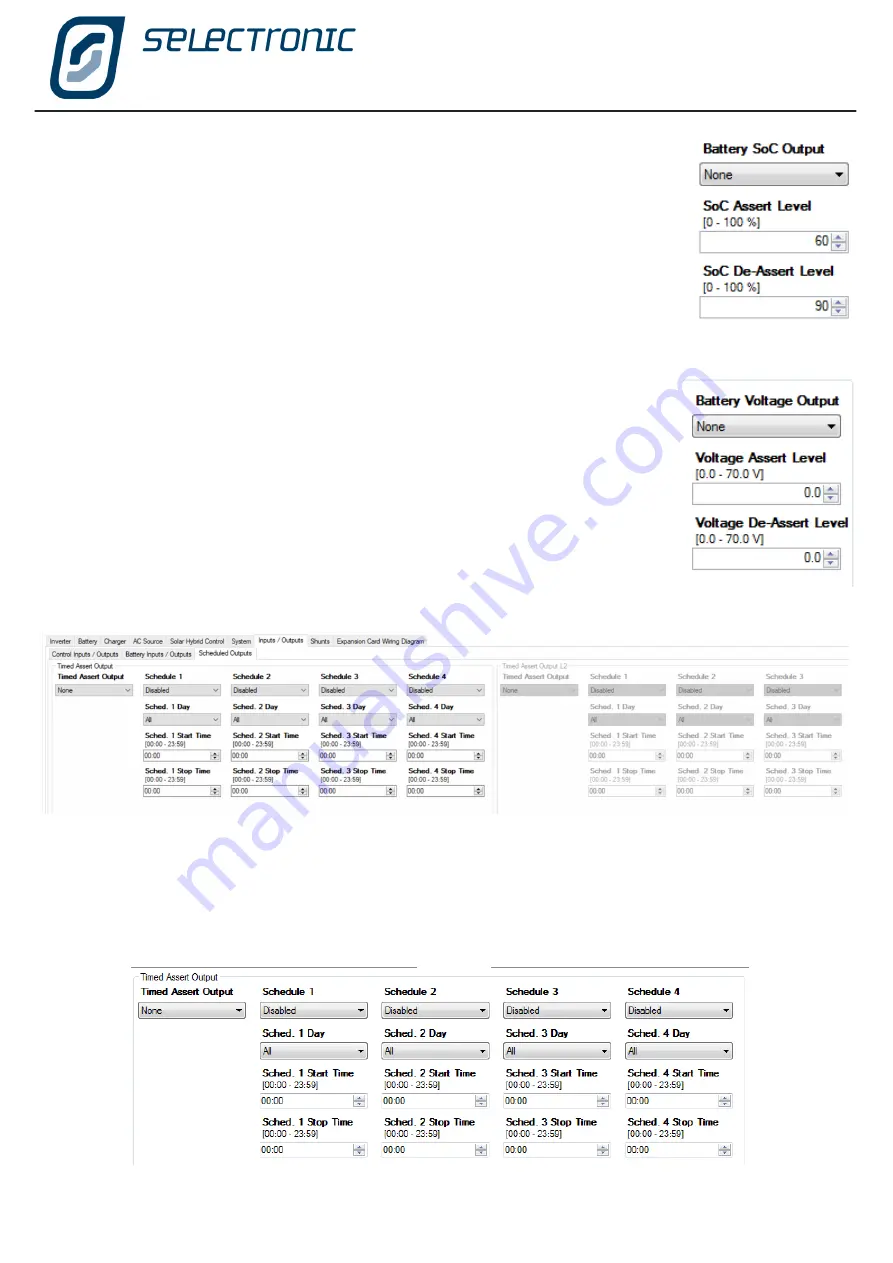
Timed Assert Output

 schedule similar to the generator run schedule is also provided for a digital output. 

This facility allows you to control the regular operation of appliances around the home. A typical example would 

be to turn on a watering system every night for a fixed period.

In a Powerchain Configuration a Timed Assert output can be set for each phase.

Battery SoC Output

 initiates the chosen output when the

 SoC Assert Level

 reaches 

the programmed SoC Assert Level then switches off the output when the 

SoC De-

Assert Level

 is reached.

If the

 SoC Assert Level

 is lower than the 

SoC De-Assert Level

 then the output will 

become active when the battery SoC drops below the 

SoC Assert Level

 then de-

activate when the battery SoC rises above the 

SoC De-Assert Level

.

If the

 SoC Assert Level

 is higher than the 

SoC De-Assert Level

 then the output will 

become active when the battery SoC rises above the 

SoC Assert Level

 then de-

activate when the battery SoC drops below the 

SoC De-Assert Level

.

The 

Battery Voltage Output

 setting is similar to the prior setting but is based on 

battery voltage instead of state of charge.

Summary of Contents for SP PRO 2i Series

Page 1: ...Instruction Manual for SP LINK Configuration and monitoring for SP PRO series 2i ...

Page 2: ...26 Firmware Update 27 Configuration Settings 32 Quick Start 33 Inverter Settings 34 Battery Settings 35 Charger Settings 37 AC Source Settings 40 AC Input 40 Power Quality DRM 42 Generator Auto Start 45 Generator Schedule Start 49 Generator Control Settings 52 Solar Hybrid Control Settings 54 System Settings 57 Input and Output Settings 61 Shunts Settings 68 Expansion Card Wiring Diagram 69 Save a...

Page 3: ... that we know this product can provide A PDF copy of this manual may be downloaded from the Selectronic web site www selectronic com au and is also included within the Help menu of the SP LINK software You will notice that throughout the manual these symbols will be repeated These symbols are very important This symbol indicates danger Failure to observe this warning may result in serious injury o...

Page 4: ...to suit your particular installation Install SP LINK software download from www selectronic com au onto a PC computer We suggest these steps are done before heading to the installation site Once on site simply unpack the unit mount it on a wall connect the appropriate cables then use the Wizard in SP LINK to configure the SP PRO and you ve got power As a safeguard the SP PRO inverters will not sta...

Page 5: ...he electrolyte either valve regulated or gel Flooded Battery A lead acid battery with access caps for maintaining the electrolyte Lithium Battery A battery based around lithium technology An example is Lithium Iron Phosphate LiFePO4 Aquious Battery A battery with salt electrolyte such as the Aquion brand of battery Managed Battery A battery with a Battery Management System that communicates with t...

Page 6: ...low instructions to update the SP PRO firmware STEP 6 Return to the easy start guide and select Site Configuration Wizard being the first entry STEP 6 Follow the steps in the Site Configuration Wizard to create a configuration for the SP PRO STEP 7 Review the Summary of Settings screen to ensure your newly created configuration details are correct STEP 8 When the wizard is complete you will be at ...

Page 7: ...d you do not have to be connected to an SP PRO inverter Once you have loaded SP LINK onto the computer you can pre configure and store on the computer the site information and configuration settings These are then ready to transfer into the SP PRO inverter after it is installed When you first open SP LINK the Splash screen will appear Once SP LINK has loaded the screen will disappear and the How t...

Page 8: ...ng the most common tasks in SP LINK Simply choose one of the three options or select from Recent Sites to open the saved information on an already configured SP PRO This window appears every time SP LINK is started and can also be accessed at any time via the File Site Information New Easy Start Guide menu or Ctrl N short cut ...

Page 9: ...nected to each phase For example in a three phase configuration with 6 SP PROs there will be 2 inverters per phase In a single phase configuration with 3 inverters there will be 3 inverters per phase Select a Detected USB Device If the computer USB port is plugged into a powered up SP PRO then its model number and serial number will be displayed Select this option Manual Configuration If there is ...

Page 10: ...grid inverter to be installed Only the Fronius or Select Sun three phase grid inverters can be installed and only on a three phase SP PRO configuration Grid Inverters per phase The number of grid inverters connected to each of the phases in a Powerchain three phase or split phase system For a single phase system enter the number of grid inverters connected to L1 Whilst the SP PRO is connected to g...

Page 11: ...ternal AC Source contactor and current transformers then enter it here Where a Grid Fail Generator Backup kit is installed then select this option PLEASE NOTE For a three phase Powerchain system three Grid Fail Generator Backup kits are installed One in each SP PRO phase manager Set the AC Source Limit to match the capacity of the AC Source connected to the SP PRO Max Grid Input Power The SP PRO w...

Page 12: ... System it is highly recommended that the system is installed with a generator To take full advantage of the SP PROs advanced generator control functions an auto start generator is recommended When a Grid fail Generator Backup module is installed in a Solar Hybrid system an auto start generator must be installed Generator Start Stop This screen is displayed where an Auto Start generator is install...

Page 13: ...on has been entered and the configuration is complete the Site file along with the Configuration details can be saved to file using the File Site Information Save menu or hit CTRL S key Connecting to the Inverter system Plug the computer into the inverter or the System Manager in a Powerchain system using the supplied USB lead then click the Connect button in the Connection Settings Powerchain Inv...

Page 14: ... refer to Firmware Update page 27 The SP PRO must be connected to the computer running SP LINK via a USB cable or an ATEN or Belkin USB to serial adaptor All the SP PROs in a Powerchain system can be updated together Make sure the SYNC cables are connected between all the SP PROs and they have DC battery volts supplied Connect the USB lead to the System manager L1 Manager then follow the instructi...

Page 15: ... a Site file There is a large window on the right side of the Site Information page click here to place a photo of the system To create a new site file for Series I units click on Convert to Series I and then proceed with remaining steps For backward compatibility for SP PRO firmware version prior to 7 0 tick Show legacy settings option SP LINK will also automatically detect this upon connection t...

Page 16: ...ant to secure the SP PRO against unauthorised monitoring or modification when the SP PRO is remotely accessible via a Modem or Network connection type Once connected the default password may be changed under Service Settings If the Login Password is lost or forgotten it can only be reset by a procedure that requires someone to be on site Contact an Accredited Integrator Saving a new site All site ...

Page 17: ... transferring into the SP PRO when connecting via SP LINK Click on the Configuration settings tab The SP PRO is a very advanced and intelligent product but don t let the large number of settings concern you Use the Site Configuration Wizard to set up the standard configurations before setting any advanced functions There is a Quick Start section near the top of the page which contains the settings...

Page 18: ...SP PRO into the computer with the supplied USB cable The SP PRO will be automatically detected by the computer and SP LINK When this occurs it will be indicated by SP LINK showing both model and serial number under Connection Settings Now we can connect to the SP PRO Either clicking the Connect button or in the Connection menu click Connect SP LINK is now connected through to the SP PRO SP LINK wi...

Page 19: ...ngs in Configuration Setting AC Source AC Input menu The right hand icon is the Output Mode of the SP PRO inverter This is red when the SP PRO output is off green tick when the output is on and in stand alone and green arrows when the output is in sync and connected to the AC Source input Five examples of Connection Status bar are shown summarised as follows A SP LINK is connected to the phase 1 L...

Page 20: ...ill be overwritten For security purposes to ensure no one can tamper with the SP PRO configuration settings you will now be asked to enter the passcode This passcode will remain active for five minutes or until the SP PRO is disconnected and will not need to be re entered until then The default passcode is 74 however you can alter this if you wish We will cover altering the passcode when we get to...

Page 21: ...configured SP LINK is connected to the L1 SP PRO SP LINK will find all the SP PRO inverters in the system and list their serial numbers in this tab The serial numbers can then be dragged and dropped into their phase and Save Assignments Double clicking a serial number in this tab will cause the RED battery LEDs to flash on that SP PRO For full details on installing a Powerchain system please refer...

Page 22: ...ing operates similar to Serial but allows for the extra delays normally present in a wireless link Serial Local connection SP LINK will automatically detect and list all SP PRO inverters plugged into the PC via their USB ports Select the appropriate SP PRO and click the CONNECT button USB Local connection Select USB when connecting via a Wireless Zigbee device The ATEN or Belkin USB to serial adap...

Page 23: ...o the SP LINK via a local Network is made using the optional SP PRO Ethernet Adaptor Lead stock code 005081 enter the Hostname or IP Address of the serial Ethernet adaptor and the IP Port number of the serial connection to the SP PRO Select live Remote Connection When a select live unit connected to the SP PRO SP LINK can connect remotely by using the select live as a gateway Just enter your selec...

Page 24: ...e you may have two sets of settings for the inverter saved within SP LINK one for NORMAL everyday use and one for HOLIDAY use In the holiday file you may have included automatic garden watering switching security lights on and off or even switching off the inverter for periods of time Changing these settings is as easy as browsing the saved files through the FILE SITE INFORMATION ASSOCIATE EXISTIN...

Page 25: ... Seeking support assistance from your Selectronic Accredited Integrator or from Selectronic Support please perform a Download All and email The zip file contained in the download directory Download Events Download just Event records what happened and when Download Detailed Data Download just the Detailed data averages of all parameters like AC Load and Battery Voltage Download Daily Summary Data D...

Page 26: ...defined graphs or a customised graph with any choice of Performance Data plus displays all the Event logging and Daily Performance Data The Events tab lists all the Operational and Alert events along with their time stamp and a snap shot of the readings at the time The Operational events occur during normal operation of the system An Alert event normally indicates that there is an issue with the s...

Page 27: ... button 4 Save Configuration settings File Configuration Settings Save SET STRING INVERTER If the system is using or will use Managed AC Coupling with a Selectronic Certified grid inverter then it is important to set the String Inverter setting and configure the SP PRO before Firmware Update Once this is done the Firmware update process will automatically selected the compatible firmware See Strin...

Page 28: ...mware from file then they need to be done one at a time Step 2 Check that the Current SP PRO firmware Information and the New firmware Information are correct before proceeding If you wish to Automatically restart SP PRO if firmware update is successful then check this box WARNING During the restart AC LOAD will be interrupted Click Program SP PRO SP LINK will begin the update process There are se...

Page 29: ... by default OR Set the Scheduled Restart Time in 24hr format when a few minutes of interruption in power is least inconvenient Click Set Scheduled Restart The SP PRO is now set to restart at that time and will continue to operate normally If you change your mind about the scheduled restart time click Cancel Scheduled Restart then set a new value Or if you click Restart SP PRO Now the inverter will...

Page 30: ...ct SP LINK to the SP PRO For existing systems load the saved Configuration file into SP LINK and make any required changes to your configuration settings Check the String Inverter setting as this may have changed during the firmware update process See String Inverter on page 59 For new system it is recommended that the Site Configuration Wizard be used now to configure the SP PRO For updates from ...

Page 31: ...SP LINK Using SP LINK Doc OI0005 Rev26 2020 31 Blank Page ...

Page 32: ...ng point The Configuration Settings are divided into named sections indicating the types of settings within them Each tab highlights a different configuration area within the SP PRO To access these settings click on the various section tabs Settings can be changed by either clicking on the drop down list or directly changing the value Every time you change a setting the title of that setting becom...

Page 33: ...pacity plus this value State of Charge SoC control gives you the option of controlling the system with either battery state of charge or battery voltage It is important to note that for State of Charge control to operate correctly the SP PRO must be able to read and monitor any charge or discharge of the battery external to the SP PRO External current shunts will need to be installed for all DC ch...

Page 34: ...only the energy coming from the battery As an example in an AC Coupled system with no AC Source 2 kW of AC Load and 2 kW of solar there will be NO load on the battery so the DC shutdown will be at the Battery 0 Load voltage Recovery Voltage When the inverter shuts down due to low voltage this setting is the voltage at which the inverter will start up again It is wise to make this voltage high enou...

Page 35: ...bsolute maximum battery charge voltage Over Target Charge Current Trip is the percentage over the battery charge target current at which the SP PRO will trip any Managed AC coupled Solar to zero output This setting is used for Lithium battery or similar technologies that have an absolute maximum battery charge current Trip Delay When the charge voltage or the charge current exceeds the Over Target...

Page 36: ...ss 1 to Softness 6 with Softness 6 being the softest setting This setting is only effective with battery technologies that have an inherently high internal impedance such as aqueous type technologies Using this setting with serviceable lead acid or lithium battery technologies may cause unintended charger operation and in some cases over voltage shutdowns Mid Point Monitoring is a function designe...

Page 37: ...remain at or below this level for 2 minutes to switch to Initial This ensures that short term loads do not prematurely cause the charger to reset to Initial The setting will turn RED when it exceeds the lowest float voltage either Float or Long term Float minus 5 for Lead Acid or 2 for Lithium or Custom Battery Types Care should be taken when setting in the RED region to ensure the Float or Long t...

Page 38: ...han in the initial stage ABSORPTION STAGE is the part of the charge process that allows the batteries to maximise the effect of the previous charge stages This stage is normally set to a higher Voltage than the two previous stages but a lower charge Current The Max Time it would remain in this stage is longer again than the previous stages This section has a further level of control in that it wil...

Page 39: ...ocess is sometimes called gassing that is when the batteries sound as if they are lightly boiling In flooded cells this bubbling helps to circulate the electrolyte fluid within the cells The Equalise stage will raise battery voltage to the equalise Voltage level and maintain this voltage for the equalise Time The equalise Current will not be exceeded If using Sealed batteries the EQUALISE STAGE ma...

Page 40: ...avg This setting is only used in a Solar Hybrid system For off grid systems set it to the maximum value of 264V If the 10 minute average of AC Source Voltage goes above this value then the SP PRO will disconnect from the AC Source The default of 255V is suitable for Australia Set this to 248V for New Zealand Reconnect Delay In a Solar Hybrid system the time the AC Source is in tolerance before re ...

Page 41: ...xternal current transformer is entered in External CT See separate Installation instructions TN0057 available from the web site under the Support tab The AC INPUT LOGGING is a Quality of Service monitoring function which sets the Peak Voltage threshold at which the inverter will record a performance data event Peak Voltage of AC rather than RMS 240V AC has a peak voltage of 340 V If you have parti...

Page 42: ...d Ramp Down Rate settings When the battery charge drops below Minimum SoC export will be prohibited as there will not be enough energy in the battery for a ramp down event Minimum SoC is limited according to the Battery Capacity Shutdown SoC and Ramp Down Rate Maximum Export Power is set to equal the maximum capacity of the installed PV solar Voltage Balance Mode is normally disabled where the pow...

Page 43: ...output based on the Power Factor Var Mode setting Power Factor Var mode Fixed AC Inverter p f default setting This mode is used when the SP PRO is installed as a Solar Hybrid grid connected system and the inverter is required by the Utility to provide support power at a non unity power factor Support Power Factor Set the value of the required power factor and the phase of that power factor for whe...

Page 44: ...source reactive power as a percentage of the SP PRO s 25 C power rating according to this setting DRM 7 Reactive Power When DRM 7 is active the SP PRO will sink reactive power as a percentage of the SP PRO s 25 C power rating according to this setting The Power factor Var settings are from the Network s perspective As the grid voltage falls below the Leading Var Start Voltage the vars generated by...

Page 45: ...fety net the SP PRO will always start the generator based on battery voltage regardless of the battery SoC or the status of the Generator Lockout When the battery voltage drops below the On Low Battery Voltage settings the generator will start and run for the Minimum Run Time On Low SoC When the On Low SoC is enabled and the state of charge falls below Start SoC at any time during the GENERATOR LO...

Page 46: ...is prepares the system for the night ahead ON SoC RENEWABLE PREFERRED is designed to monitor the input from the solar array and on a day when the renewable sources may be low in output on a cloudy day or a day with no wind start the generator at a lower state of charge to ensure the batteries do not get too low This setting allows you to set a Start SoC percentage and a Stop SoC percentage that wi...

Page 47: ...ou would have expected Throughout the whole day there is always the lower Generator Lockout Override safety net level that will not allow the batteries to get totally flat An Accredited Installer can help you arrive at the most fuel efficient program to suit your particular needs The above system of Generator Auto Start SoC Start and Stop levels prevents the generator from charging the battery ban...

Page 48: ...e site load then no power will be coming from the battery bank i e Battery Load is 0 kW and the generator won t be started On 15 min Load is similar to the previous screen except the settings take effect if the average load exceeds the preset Battery Load limit for more than 15 minutes We previously discussed mid point monitoring and its ability to help determine a battery fault This screen allows...

Page 49: ...or to run such as when a regular plant watering routine requires pumps to run the program contains the ability to predetermine four different schedules Each of the four Schedules specified as Sched x in the following examples can be enabled or disabled Using Sched x Day you can choose a day of the week all weekdays all weekends or everyday All ...

Page 50: ...uled time or if disabled the generator will continue to run if a full charge cycle has not been completed or until all other generator turn off criteria have been met As an example lets imagine you run a yoga class every Saturday morning and you wish to run a reverse cycle air conditioner for the period of the lesson You may choose to run the generator during this period to prevent stress on the b...

Page 51: ...SP LINK Configuration Settings Doc OI0005 Rev26 2020 51 INVERTER UNAVAILABLE SCHEDULE This is a legacy setting and is not available with Powerchain features ...

Page 52: ...the length of time after the generator starts before the generator is connected Transferred to any load This is then followed by the Warm Up Time the length of time after the Pre synchronised warm Up Time before a charging sequence starts Once synchronised the AC Load is transferred to the generator during the Warm Up Time The staged warm up sequence allows the generator to circulate the oil withi...

Page 53: ... 6kW the generator will continue to run The Start output Delay setting determines the length of time after the generator run signal is initiated by the SP PRO either by an external request load requirement or by a battery charge requirement before the generator start pulse is initiated Start output Time is the length of time a start pulse is sent This output can be used in a pulse start pulse stop...

Page 54: ...ATION controls when the limits and controls set for that Priority schedule become operational ACTIVATION is divided into two sections Enable Date and Time Activation setting Use Begin Date and End Date to set the inclusive date range over which you want this Priority Schedule to be active By default the range is all year and only requires adjustment if part of a year such as summer is required Day...

Page 55: ...rs in a Powerchain configuration Only the System Manager L1 manager controls this function INVERTER CONTROL manages the AC Load Battery Support by controlling the amount and limit of battery support AC Load Support Limit sets the maximum AC Load power that can be supported from the battery bank when the SP PRO is synchronised to the AC Source Grid supply This power does not include any contributio...

Page 56: ...mit The Restricted Charge Limit setting The inverter Charge power rating temperature dependent The Charge Limit is displayed in the Data View Now tab and is the lesser of The Renewable Power available for charging Renewable Load power The Restricted Charge Limit setting The inverter Charge power rating temperature dependent It should be noted that Charging On setting with a Grid Input limit of 0kW...

Page 57: ...isabled Beeper will not activate for any alarms The AC Source disconnect beeper provides an alert signal five short beeps once per minute if the SP PRO is not synchronised to the AC Source This is disabled by default and must be Enabled if you wish the system to signal that it is running on battery supply during grid outages The Year to Date feature of the unit is used to monitor the systems perfo...

Page 58: ...nt rises above the SP PRO s active charge voltage or current target When the battery voltage or charge current drops below the battery charge target the output frequency of the SP PRO will ramp back down Enabled The frequency will ramp all the way to the Frequency Ramp Limit before ramping down again to the nominal Frequency MicroGrid The frequency will start ramping down again as soon as the char...

Page 59: ...AC Bus Islanding Power Limit limits the output power of all the connected compatible solar inverters when the SP PRO is islanding or Off Grid In a multi phase system this setting is per phase For example in a three phase system an Islanding Power Limit setting of 10kW will limit the total solar output for the system to 30kW when islanded This parameter is useful in Solar Hybrid systems with small ...

Page 60: ... managers When a three phase Powerchain system is configured three phase Selectronic Certified string inverters may be used being the Fronius Symo and the SelectSun Up to five three phase string inverters may be configured on each phase manager giving a maximum of fifteen 15 string inverters per system Number of Devices sets the number of compatible inverters that are connected to the SP PRO in a ...

Page 61: ...ered essential if say phones or a fire pump MUST be operated Normal Alternate AC Input Power Selector When a second AC Source with a different capacity to the primary AC Source Normal is available to the system use this setting to set the input that you wish to use to select the alternate power level The alternate source power level is configured in Alternative AC Source Power back in the AC Input...

Page 62: ...he full range of output options The analogue input is set in Analogue Control Input An analogue input differs from a digital input in that instead of reacting to an on off type signal as a digital input does An analogue input reacts to a pre programmed upper and lower voltage level which are set in Input Assert Level on voltage point and Input De Assert Level off voltage point As an example if a s...

Page 63: ... start the generator when there is no fuel The Generator Fault input can detect signals from the generator control system to either stop the generator or prevent the SP PRO from attempting to start the generator when a fault is present in the generator In Generator Outputs you can configure the Run and Start outputs to suit the starting requirements of the motor generator The Generator Run Output ...

Page 64: ...r of the day Similarly AC Load Power Output has been allocated to Digital Control Output 2 which will be activated if the AC load on the system exceeds the Power Assert Level of 4 5 kW for 30 seconds External Regulator Bypass Output can be used to control a relay that will bypass the solar or wind generator regulator to allow the full renewable output to be forwarded to the battery or exported to ...

Page 65: ... Contactor CT functionality This control is also used to provide a grid failure alarm The output is active during a grid outage AC Source in Tolerance Output configures an output to become active when the AC Source voltage and frequency are in tolerance according to the settings in AC Source AC Input tab This output was used in a legacy mutiphase configuration where it is a requirement for all pha...

Page 66: ... output when the battery voltage reaches the Hi Battery Alert set point in the Limits section in the Battery Settings section Battery Charger Inputs are used in a variety of ways to help integrate the SP PRO with other renewable chargers All work in a similar way but just move the charger to a different charging mode Care must be taken when using these inputs as improper use can prevent the charge...

Page 67: ...vel reaches the programmed SoC Assert Level then switches off the output when the SoC De Assert Level is reached If the SoC Assert Level is lower than the SoC De Assert Level then the output will become active when the battery SoC drops below the SoC Assert Level then de activate when the battery SoC rises above the SoC De Assert Level If the SoC Assert Level is higher than the SoC De Assert Level...

Page 68: ...ritical Load Unidirectional Measure DC loads Always assumes load current so polarity not critical Dual Bidirectional Measure DC charging and DC loads The polarity of the shunt IS critical Multiple SP PROs Bidirectional Legacy setting that was previously used in Off Grid multiphase three phase of split phase Not used in Powerchain systems Log Only Bidirectional Used to measure and log a current tha...

Page 69: ...e may vary depending on SP PRO model Click Change Card Type to change display to suit the model Default configuration shown Save and Configure Settings The configuration settings may now be saved to file or sent to the SP PRO using the Configure SP PRO button To save the SP PRO configuration settings click on File Configuration Settings Save To configure the SP PRO ensure SP LINK is connected via ...

Page 70: ...story of all modes of operation of the power system These options are Customer Interface Quick View real time summary of SP PRO system Integrator User Interface Data View real time detailed information of what is occurring Now Today and what has occurred Historically Integrator User information Performance Data Historical records for displaying graphically ...

Page 71: ...labelled L1 L2 L3 and Split along with a Manager Worker drop down box as applicable These buttons are used to access the displayed Data View screen for each of the individual inverters For example click on L2 and all the screens will display data applicable to the SP PRO on L2 phase manager Each section contains details for Now Live values of voltage current and power plus system status Today Hist...

Page 72: ...shown is for a Solar Hybrid On Grid system The real time overview values shows how much power is being produced AC Solar and exported Export Power and Export Today as well as the present consumption AC Load Power and AC Load Today The battery condition Battery SoC and Battery Voltage is also indicated The overview for a Off Grid system varies slightly such that the Export Power and Export Today ar...

Page 73: ...EMP Yellow SP PRO is approaching an over temperature condition Red SP PRO has shutdown due to an over temperature condition SHUTDOWN Yellow SP PRO is approaching a shutdown condition Red SP PRO has shutdown ATTENTION Off Normal Yellow Attention Required Fan Service Request Flashing Yellow Clean Fan Fan Fault or Capacitor Service Red Immediate Attention required Flashing RED Unit Fault See Attentio...

Page 74: ...tteries 2 Turn off all the loads connected to the SP PRO If this is not done then the AC Coupled Low DC Recovery mode will exit within 5 seconds 3 Long Press ON button Twice The SP PRO will go into AC Coupled Low DC Recovery mode and come on to power up the AC coupled grid inverters The battery LEDs on the front of the SP PRO will flash red when in this mode If the AC coupled solar does not start ...

Page 75: ... generic AC coupled solar power AC Load Voltage The AC voltage being delivered to the load AC Load Frequency The frequency of the AC voltage being delivered to the load If the Attention indicator is flashing on the front panel check the Attention Required area to find out the cause For further information see Appendix One Alert Messages on page 98 The table in this section outlines all the SP PRO ...

Page 76: ... is in Amps Available Power is the difference between the Power reading and the AC Source Power setting in the SP PRO The SP PRO will automatically reduce the charge power to the batteries or draw power from the batteries as required to keep the AC Source power below the AC Source Power Setting Network Power Meter displays the total power as measured by an externally connected three phase power me...

Page 77: ...of the SP PRO AC Load Support Limit The maximum AC Load power that can be taken from the battery bank This limit will be breached if the SP PRO is not synchronised to the AC Source input Battery Charging Shows the status of the SP PRO Battery Charging function Restricted Charge The Charge power is restricted to the Charge Limit within a Priority Schedule Charger Off The Charge is off and wont char...

Page 78: ...l power consumption by the site during that day AC Input Energy shows the total contribution by the generator or the mains grid while Hours of AC Input records the running time of the generator or the length of time the mains grid was connected to the SP PRO Inverter Run Time is the length of time the inverter has run today this should be all the time unless you have programmed in an Inverter Lock...

Page 79: ... History Tab The next tab is the DC HISTORY screen As the name implies this screen gives you data from the previous day the last seven days the last 30 days the last year and the whole period since installation All the input to the battery bank All the output ...

Page 80: ... the system never reaches float you may need to increase the solar array size if the system regularly enters float before lunch you may be able to consider adding extra luxury loads to the system SoC will be set to 100 when Float Charging Mode is entered This panel gives a picture of the effect that Shunt 1 has had on the system For the sake of clarity we will assume that Shunt 1 measures the sola...

Page 81: ...In the case shown DC Loads This panel shows historical data of all of the DC energy that has passed into or out of the inverter This panel also gives you the ability to accumulate this data from a date you determine By pressing the Reset tab all totals in this reading are zeroed and accumulation of data starts again on the date of the reset A particular feature of this panel is the ability to comp...

Page 82: ...y the home to the power system This is the total AC input contributed by the motor generator or by the mains grid AC History Tab The AC HISTORY SCREEN as with the DC History screen gives you data from the previous day the last seven days the last 30 days the last year and the whole period since installation ...

Page 83: ...ow many hours the generator has run or for how long the mains grid was connected In grid connected systems you can monitor the amount of energy exported to the grid comparing today s total with the last week month or year Total AC Coupled Solar Energy input to the system ...

Page 84: ...to determine its significance Midpoint Voltage is a measurement of half the battery voltage at the battery terminals when the battery sense pre charge wiring is installed If this value is not half the Sense Voltage then the batteries need equalising or there is a faulty cell Midpoint Error is a measurement of the error in the midpoint voltage as a Cable Loss is the amount of power that is dissipat...

Page 85: ...s a measurement of the real power being passed through the inverter between the DC sources Battery bank and DC coupled charging sources and its AC output A positive value the inverter is charging the battery A negative value the inverter is supporting the load from the DC sources Reactive Power is a measure of the VArs being provided by the SP PRO Apparent Power is a measure of the inverter s AC v...

Page 86: ...gh to 5 when connected display all of the data fed back from each Managed AC coupled grid connect unit The RS485 Device Address shows the Address that has been configured in that particular grid inverter For KACO or Fronius inverters this is address 1 to 5 for AC Solar 1 to AC Solar 5 respectively For ABB inverters the RS485 Device address is 2 to 6 respectively When ABB solar grid inverters are c...

Page 87: ...the new features made available Total Run Time tells you the total number of hours the inverter has run If the SP PRO is fitted with a Comms Card 2027 then the card s serial number hardware revision and firmware revision is recorded under Comms PCA Serial Otherwise this section is greyed out Factory Set Options displays the configurations that have been set in the factory These settings cannot be ...

Page 88: ...rge Voltage Limit The maximum charge voltage allowed at that time Battery Current The battery current at that time Positive current is charging negative is discharging State of Charge The battery SoC as read from the BMS BMS Model The model number of the BMS or battery connected to the SP PRO State of Health Indicates how much of the battery has been used Alarms and Warnings Displays any alarms or...

Page 89: ...he total of all the installed managed AC coupled solar in the system DC on L1 DC on L2 DC on L2 DC on Split Gives the contribution of DC current from each of the phases in the system Only the applicable phases are displayed AC on L1 AC on L2 AC on L3 AC on Split Gives the contribution of AC power from each of the phases in the system Only the applicable phases are displayed AC coupled Solar on L1 ...

Page 90: ...d output functions are programmed and allocated in the SP PRO This display is only active when the are connected to the SP PRO The Unused Features display lists all input and output functions that have not been allocated to an input or output Expansion card picture may vary depending on SP PRO model Click Change Expansion Card Type to suit the model ...

Page 91: ...SP LINK Performance Monitoring Doc OI0005 Rev26 2020 91 BLANK PAGE ...

Page 92: ...5 Rev26 2020 Certain readings within the SP PRO must be correctly configured at the time of the original setup These include the time and date an approximation of the state of charge and that the current shunts are zeroed Service Settings ...

Page 93: ...l be corrected This function is not used when the SP PRO is communicating with a battery as the SoC is read directly from the BMS Login Password The Login Password is only used when connecting to the SP PRO A separate password is used to change configuration settings Settings Password If you are concerned that the default login password does not provide the level of security for any access to the ...

Page 94: ... inputs and outputs are switched off that is no solar wind or other inputs coming into the system and all DC loads are switched off then the ZERO SHUNT 1 and ZERO SHUNT 2 buttons should be pressed The figures above the buttons indicate what the on board computer in the SP PRO perceives the relative current to be before zeroing Fan Type The cooling fan within the SP PRO is a long life high quality ...

Page 95: ...cluded as secondary protection when the AC Source is connected via a removable plug to the generator or mains grid The primary protection for a plug in AC Source must be a shrouded plug that prevents contact with the plug terminals when removed from the socket This feature should only be disabled if the AC Source in hard wired to the SP PRO and the wiring configuration will trip the AC Safety Moni...

Page 96: ...to 5 0kW and there is 3kW of Solar being produced at the time only 2kW of support power will be available from the battery giving a total of 5 0kW In multi phase systems this setting is per phase Export Limit is the same function as a Factory Set Export Limit with the exception that it can be set by the installer If the Export Limit is set higher than any Factory Set Export Limit then the latter w...

Page 97: ...SP LINK Service Settings Doc OI0005 Rev26 2020 97 Blank Page ...

Page 98: ... AC Source Safety Monitor Alert Neutral and Earth are not at same potential The inverter has detected either a poor EN connection or missing EN connection in the AC Source wiring Call system installer to check the voltage between the Earth and Neutral of the AC Source connections at the Inverter If voltage 1VAC then track down the wiring fault Service Settings AC Input Safety Monitor group AC Sour...

Page 99: ...e are no faulty cells in the battery bank and to take measures to reduce battery ambient temperature Battery Over Temp Protection Limit Charge Above Battery Over Temp Protection Alert cleared The battery temperature has dropped below the Over Temp Protection limit Battery Over Temp Protection Limit Charge Above Battery Management Alarm The Battery Management System within the battery has sent an a...

Page 100: ...hase rotation or phase angle is incorrect Call your installer or appropriately qualified personnel to check all AC Source wiring and AC Source supply for correct voltage phase and phase rotation Inverter AC Source out of phase Off Above condition has cleared Inverter AC Source out of tolerance Beeper On When the AC Source Disconnect Beeper is enabled and the AC Source is outside the set limits as ...

Page 101: ... close to Shutdown voltage and shutdown is imminent The loads on the system maybe exceeding the charging source Firstly reduce all the loads on the system to the minimum and start your generator Check that all the charging sources such as PV solar and generator charging are functioning correctly If there is a problem with one of the charging sources then contact your installer If all is OK then yo...

Page 102: ...s cleared Powerchain AC Source Alarm on Phase L2 Check L2 Dataview Now for alarm details Powerchain AC Source Alarm on Phase L2 Cleared Above condition has cleared Powerchain Alert Alarm on Phase L3 Check L3 Dataview Now for alarm details Powerchain Alert Alarm on Phase L3 Cleared Above condition has cleared Powerchain Shutdown Alarm on Phase L3 Check L3 Dataview Now for alarm details Powerchain S...

Page 103: ... manager has lost SYNC comms with L3 Phase Manager Check SYNC connections and cables between inverters in Powerchain Powerchain No comms to Phase Manager L3 Cleared Above condition has cleared Powerchain No comms to Phase Manager Split The System Mananger L1 manager has lost SYNC comms with Split Phase Manager Check SYNC connections and cables between inverters in Powerchain Powerchain No comms to...

Page 104: ...match the setting in the Service Settings Contact your installer to either change to position of the safety monitor switch or change the setting in the Service Settings using SP LINK Service Settings AC Input Safety Monitor group Service AC Source Safety Monitor State matches State of Actual Switch Above condition has cleared Service Fan Alert Fan not spinning Cooling Fan is not spinning due to ob...

Page 105: ...nic com au service Service Output Capacitor life end alert cleared Above condition has cleared Service Power Module 1 Capacitor Life Alert Life at or above 95 The internal capacitors have reach the end of their rated life Recommend inverter returned to Service for capacitor replacement Contact Selectronic service at http www selectronic com au service Service Power Module 1 Capacitor Life Alert cl...

Page 106: ...g Above condition has cleared System AC Load Voltage Alert Volts detected from unknown source There is an AC voltage on the inverter load terminals when the inverter is off Caused by either a stuck AC contactor or wiring fault Contact your installer to remove all connections to the AC load terminals If Alert persists then your inverter has a stuck contactor and will need a service Contact Selectro...

Page 107: ...tact your installer to check battery temperature sensor and its wiring Measure sensor with multi meter approximately 2k ohms at 25C System Battery Temp sensor ok was shorted Above condition has cleared System Common defaults loaded The user has initiated a Load Defaults from the front panel of the inverter System Hi Battery Shutdown AC Coupled Fault Only applies to AC coupled systems Managed or Ge...

Page 108: ...reless devices between the SP PRO inverter and the Selectronic Certified grid inverter System AC Coupled Inverter 2 communication Fault Cleared Above condition has cleared System AC Coupled Inverter 3 communication Fault The RS485 communications with AC Coupled Inverter 3 has been lost for longer than 18 hours It is normal to lose communications overnight when the AC Coupled Inverter shuts down so...

Page 109: ...ters come back on Check to see which SP PRO inverter is causing the shutdown by checking its alarm status via SP LINK or remote communications If using SP LINK then check Attention required box to determine cause System multi phase system fault forcing shutdown Off Above condition has cleared System multi phase system fault On Only applies to three phase or Split phase systems There is a fault in ...

Page 110: ...y out a service on the generator or to replace the faulty generator System Synchronisation Fail Cleared for retry Above condition has cleared System Synchronised Overload Shutdown Inverter has shutdown from over current when connected and synchronised to the AC Source Caused by a disturbance in the AC Source voltage or distorted AC Source voltage Fault indicates a poor AC Source voltage waveform C...

Page 111: ...rvice Unit Control PCA Factory defaults loaded The user has initiated a Load Defaults from the front panel of the inverter Unit Generator button fault button stuck down Stuck button on the front panel of the inverter If fault persists contact service For persistent fault contact Selectronic service at http www selectronic com au service Unit Hi DC Voltage Fault Battery voltage has risen to an abno...

Page 112: ...Caused by hardware glitch If event persists then contact Service For persistent fault contact Selectronic service at http www selectronic com au service Unit Power Supply Shutdown Hardware Fault within the inverter Inverter will not run For persistent fault contact Selectronic service at http www selectronic com au service Unit Power Supply Shutdown cleared Above condition has cleared Unit Real Ti...

Page 113: ... high There is a fault in the inverter s internal temperature reading Inverter will need a service For persistent fault contact Selectronic service at http www selectronic com au service Unit Transformer Temp Fault cleared was too high Above condition has cleared Unit Transformer Temp Fault sensor reading too low There is a fault in the inverter s internal temperature reading Inverter will need a ...

Reviews: