10
Selectronic Australia
Rev 41 - Dec 2022
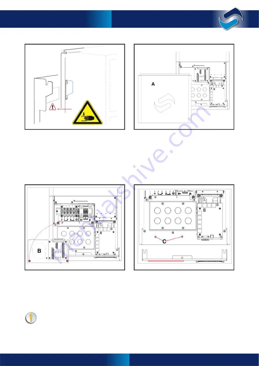
Installation
Installing SPMC models
3
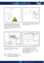
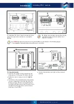
– Leave access cover (
A
) in place. Lift inverter
from underneath whilst stabilising top. Inverter is
top-heavy and gloves must be worn. Mount the
SP PRO on the mounting plate by first hooking the
top of the inverter over the projections and lowering
it into position. Care should be taken to observe
pinch point warning.
4
– With a T25 Torx driver, remove the access cover
(
A
) by unscrewing the two M5 Torx screws at the
bottom of the SP PRO.
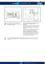
5
– Using the T20 Torx driver, remove the
terminal cover and the expansion card (
B
) by
undoing the two screws.
6
– The lower gland plate can be removed if
required to give greater access to wiring
terminals using T25 Torx driver. NB, side screws
need only be loosened.
Secure the bottom of the SP PRO to the mounting
plate with two M5 Torx screws.
(
C
) on above diagram
Installing SPMC models
7
-
STOP:
Detailed instructions for wiring
the SP PRO are contained on the
following pages. These
must
be followed
before proceeding with installation.


