13
Selectronic Australia
Rev 41 - Dec 2022
Installation
Installing SPLC models
2
- Cable entry is either from below or wall entry. Gland
plates are interchangeable. Gland plates secure to the
underside of unit base or to the inside of the mounting
plate using four T25 Torx screws.
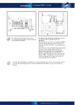
4
- Undo ten bolts (7/16”) to remove sides from
the packing base. Undo eight bolts (7/16”) to
remove clamps from handles.
Do not
remove
front access cover.
Heavy:
Take care when lifting – 105kg
Sharp:
Use gloves – handle edges sharp.
Top-heavy:
Secure unit when standing unit
upright. Stand unit upright using handles.
Rear air outlet mesh cover:
Fit and secure with
six thumb screws.
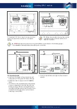
6
- Using T25 Torx driver, remove the cover by
unscrewing two screws at the bottom of the SP PRO.
Any wiring via the rear gland plate (attached
to mounting bracket) can be roughed in
before mounting the SP PRO.
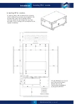
3
- See diagram on previous page.
Choose a suitable weight-bearing and
temperature-resistant surface to install the
mounting plate. Mounting
must
be to solid
timber studs, solid timber, brick, masonry, or
other load-bearing wall.
Do not
mount
directly to plaster. Max temperature is
a30°C, weight is 115kg. The plate
should be mounted at a convenient level.
There should be no obstructions to the clear
passage of air.
Wall or cavity cables may now be fitted
through gland plate.
5
- Mount the SP PRO on the mounting plate by first
hooking the top of the inverter over the projections
on the mounting plate and lowering it into position.
Care should be taken to observe pinch point warning.
Secure the bottom of the inverter to the mounting
plate with two M6 bolts provided.


