18
Selectronic Australia
Rev 41 - Dec 2022
Installation
Battery Wiring (DC) Preparation
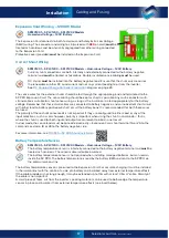
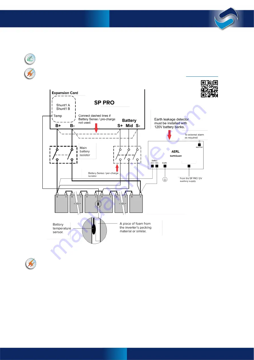
The below schematic diagram shows the main battery isolator, Battery Sense / pre-charge isolator and
included temperature sensor.
It is recommended that the Battery Sense / pre-charge connections (S+, Mid and S-) are used and
wired directly back to the battery bank terminals. If not, then the SP PRO battery S+ and S- terminals
must be connected to the main battery terminals B+ and B- respectively.
For 120V battery systems, installed in Australia, suitable Earth leakage detection must be installed.
The AERL EarthGuard is suitable for use with the 120V SP PRO inverter. Visit:
AC Wiring
The SP PRO belongs to overvoltage category III, meaning that it must be a fixed installation
connected either downstream (customer’s side) of or directly to the main switchboard.
Warning:
Copper wiring must be used throughout.
The SP PRO does not contain internal circuit breakers or fuses. The AC wiring must be fitted with appropriate
fusing or circuit breakers.
The AC cabling should be sized according to maximum demand through (consumed by the AC Load) and
simultaneously consumed by (consumed by the charging of batteries) the SP PRO. The SP PRO is fitted with
terminals that are suitable for accepting up to 35mm
2
(50mm
2
for SPLC models) cables. The SP PRO is rated to
63A (125A for SPLC models) current capacity and must be protected externally with circuit protection device(s)
of no greater than this.
AC wiring should be fed through the appropriate gland and terminated to the SP PRO.
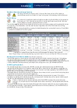
Connect the AC Load wiring to the SP PRO: Earth, neutral and active stripped back according to the table
below and connected to the AC Load terminals.
Connect the AC Source wiring to the SP PRO: Earth, neutral and active stripped back according to the table
below and connected to the AC Source terminals.
Cabling and Fusing
Diagram given as a reference only. Please ensure all
wiring complies with relevant safety standards.

