26
Selectronic Australia
Rev 41 - Dec 2022
Installation
Ancillary Components
Inputs and Output
All SP PRO models come standard with four digital inputs, three digital outputs and four relay outputs.
Additionally, the 24V and 48V models include two analogue inputs.
Each input and output is fully programmable and can be used to provide advanced functionality.
The ratings of the digital inputs and outputs are tabulated below.
Digital Inputs (x4)
Maximum input voltage 60VDC
Active when input > +10VDC; Inactive when input < +3VDC
Analogue inputs (x2)
(24V and 48V models only)
Input voltage range 0–60VDC
Relay outputs (x4)
N / C and N / O dry contacts
Maximum control voltage 60VDC
Maximum control current 500mADC (limited by internal current protection)
Digital outputs (x3)
Maximum control voltage 60VDC
Maximum control current 5mADC
Analogue Inputs
The 24V and 48V SP PRO inverters have two analogue inputs that are logged and that can be used to control
a digital or relay output, based on set input voltages. Their logged data is included in the downloadable
Performance Data download. Analogue inputs are excellent for a pyranometer or anemometer. Use this data
from these devices to confirm system performance.
Digital Inputs
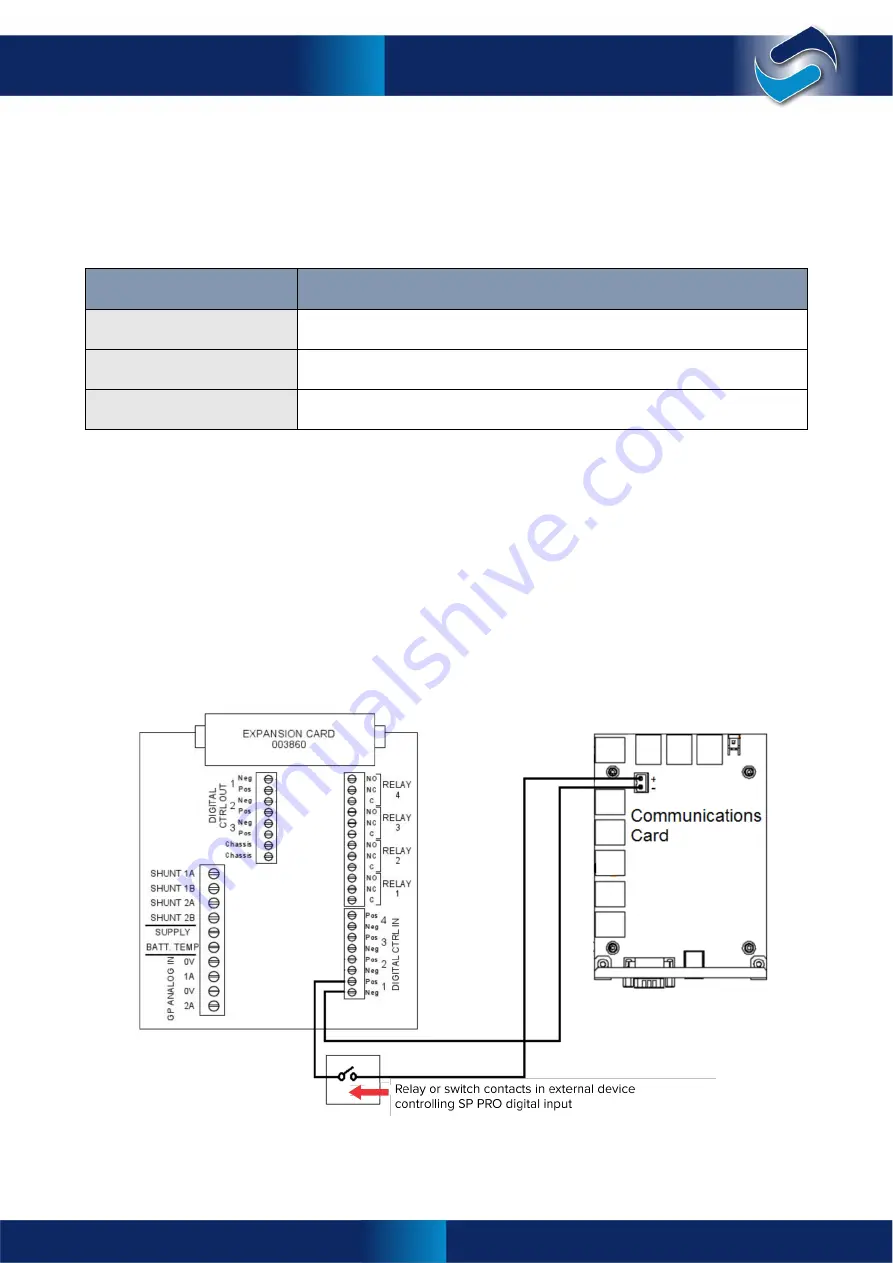
Each SP PRO has an internal 12V 0.8A supply on the Communications Card, which is suitable for controlling
the SP PRO digital inputs. The schematic below demonstrates the connections for controlling a digital input
from dry contacts on an external device.
The table below lists all of the functions available for digital inputs on the SP PRO inverter.
All the settings are in >
Configuration Settings
>
Inputs / Outputs
Ancillary Components

