57
Selectronic Australia
Rev 41 - Dec 2022
Service
Appendix A – Specifications
Standards Compliance
IEC 62109-1:2010 Ed. 1.0
Safety of power converters for use in photovoltaic power systems – Part 1
General requirements
IEC 62109-2:2011 Ed. 1.0
Safety of power converters for use in photovoltaic power systems – Part 2
Particular requirements for inverters
AS/NZS 61000-6-3:2007
Electromagnetic Compatibility (EMC) – Part 6-3: Generic Standards –
Emission Standard For Residential, Commercial And Light-Industrial
Environments
AS/NZS 61000-6-4:2007
Electromagnetic Compatibility (EMC) – Part 6-4: Generic Standards –
Emission Standard For Industry
AS/NZS 4777.2:2015
Grid connection of energy systems via inverters – Inverter requirements
Includes DRM 0-8 and all optional power quality modes
AS/NZS 4777.2:2020
Grid connection of energy systems – Inverter requirements
Complies with the requirements in appendix M for Stand Alone Inverters
SPMC480-AU – SPMC481-AU – SPMC482-AU – SPLC1200 – SPLC1202 only
IEC 62116:2014
Utility-interconnected photovoltaic inverters – Test procedure of islanding
prevention measures
AS 62040-1:2019
Uninterruptible power systems (UPS) Safety requirements
(IEC 62040-1:2017 (ED 2.0), MOD)
IEC 62477-1:2012 (AMD1:2016) Safety requirements for power electronic converter systems and equipment –
Part 1: General
C-tick Australia
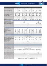
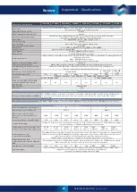
Product Specifications
Selectronic reserves the right to change specifications without notice. All ratings are at 25°C and
nominal battery voltage unless otherwise stated. The product is specified to a maximum altitude of
2,000 metres.
The RS232 ports are wired as DTE with their pinouts listed in the table below
Signal RS232 Port 1 RJ45 Pin
Signal RS232 Port 1 DB9
Signal RS232 Port 2 RJ45
1
+12V 0.8A supply
N / C
+12V 0.8A supply
2
N / C
Receive (Input) Data
Data Terminal Ready
3
Transmit (Output) Data
Transmit (Output) Data
Transmit (Output) Data
4
Signal Ground
N / C
Signal Ground
5
Signal Ground
Signal Ground
Signal Ground
6
Receive (Input) Data
N / C
Receive (Input) Data
7
N / C
N / C
Data Carrier Detect
8
N / C
N / C
N / C
9
–
+12V 0.8A supply
–
The RS485 ports are isolated from the +12V supply, from all other ports and from each other.
RS485 port 2 has an on-board termination resistor, which can be switched out using the adjacent DIP switches.
RS485 port 1 has no termination resistor and must be provided by the user as required.
Port pinouts are listed in the table below.
Pin
Signal RS485 Port 1 RJ45
Signal RS485 Port 2 RJ45
1
Signal Ground
Signal Ground
2
Signal Ground
Signal Ground
3
Data A (+)
Data A (+)
4
Signal Ground
Signal Ground
5
Signal Ground
Signal Ground
6
Data B (-)
Data B (-)
7
Signal Ground
Signal Ground
8
Signal Ground
Signal Ground
9
Signal Ground
Signal Ground
Appendix A - Specifications


