background image

Page 13

3.  Wall bands must then be installed at 2.4m(8ft.) intervals
above the intermediate wall support.

4.  Using the nut and bolt supplied, fasten the wall band
around the chimney section.  Then secure the band to the
wall using two 6d(2") spiral nails or appropriate masonary
fasteners for concrete walls.

ROOF FLASHING INSTALLATION

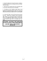
1.  Ensure that you have the proper roof flashing by checking
your roof pitch using a level and two rulers, or by using a roof
pitch card.  See figure 23.

FIGURE 23

8.  If the chimney extends more than 2m(6ft.) above the roof
deck, then roof guys are required.  Model JURGK-1 is
suitable for this application.  The draw band must be
clamped around the chimney and the two legs bolted to the
chimney.

VENTILATED
ROOF
FLASHING

SHINGLES

FIGURE 24

WARNING:  DO NOT BLOCK THE VENTILATION

OPENINGS IN THE FLASHING.

2.  A Rafter Radiation Shield is only required when the
chimney is enclosed in the attic space.  The shield is
installed from above the joist and is supported by the two L-
shaped brackets on the sides.  Ensure that the chimney is
plumb, then nail the rafter radiation shield into place through
the brackets before the roof flashing is installed.  See figure
24.

3.  Slide the roof flashing suitable to your roof pitch over the
chimney.  Place the top edge of the flashing  plate under the
shingles.  Place both sides and bottom  edge on top of
shingles.  See figure 25.

4.  Square up the flashing plate and nail in place to the roof
deck using 12 nails with neoprene washers or  cover the
heads with a suitable water proof mastic.

5.  Wrap the storm collar around the chimney above the
flashing, and secure the ends loosely together with the nut
and bolt supplied.  Slide the collar down the chimney until it
contacts the flashing guides.  Tighten the nut and bolt and
seal the storm collar to the chimney with a suitable non-
combustible mastic.

6.  The flashing and storm collar should be painted to match
the roof shingles.  This will extend its life and improve the
appearance of the installation.  Clean, prime, and paint with
suitable painting products.

7.  Continue adding chimney lengths until the proper height
is achieved.  See Chimney Installation Instructions on page
3.   Install a raincap (standard or deluxe model) and lock it
into place by turning it clockwise until tight.

OUTSIDE AIR KIT INSTALLATION
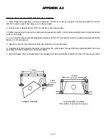
(See Appendix A-1 & A-2)

1.  The outside air kit has been has been designed to be
installed on either side of the fireplace so as to accommodate
your installation.

2.  The maximum length approved for the aluminium flexible
air duct is 4.9m(16ft.) of which  3m(10ft.) may be vertical
above the fireplace.

RAFTER

RADIATION

SHIELD

VENTILATION

SLOTS

FLASHING

STORM
COLLAR

NOTE:    AT THE TOP EDGE OF THE FLASHING

PLATE, LIFT THE SHINGLES AND NAIL THE PLATE

TO THE ROOF DECK.  THEN CEMENT THE SHINGLES

TO THE PLATE WITH A SUITABLE WATERPROOF

MASTIC.

12 INCH RULER

LEVEL

ROOF

7"

PITCH IS

7/12

FIGURE 25

Summary of Contents for 640/ZC40

Page 1: ...supervent ca 1400 California Avenue Brockville Ontario K6V 5V3 www selkirkcanada com Selkirk Canadian Operations F I R E P L A C E Installation Instructions User s Guide LISTED TO ULC S610 M87 UL127...

Page 2: ...E PLUG INSTALLATION ELBOW INSTALLATION OFFSET SUPPORTS SS INTERIOR RESUPPORT CF ROOF SUPPORT OFFSET SUPPORTS CF INTERIOR SUPPORT OFFSET SUPPORT CF ROOF SUPPORT CHIMNEY ADAPTER INSTALLATION CF ADAPTER...

Page 3: ...wires in and around the intended location of your chimney and make sure that all wires are secured at least two inches away from any chimney parts Never cut or touch any wires because a fatal shock c...

Page 4: ...enchosen removeanycombustiblematerialssuch as carpeting or vinyl floors from where the fireplace will be positioned An area for the hearth extension must also be removed 205mm 8 on both sides of the f...

Page 5: ...d at all joist levels except an open attic level Use 1 1 2 nails to attach it to the joists The shield may be trimmed but must remain 25mm 1 below or above the ceiling RADIATION DUST SHIELD 3ft 10ft 2...

Page 6: ...XTERIOR WALL FIGURE 6d FIGURE6c 15 30 45 ELBOWS 2 MINIMUM CLEARANCE INTERMEDIATE WALL SUPPORT LOCKING BAND WALL BAND 7ft MIN 30 WALL PLUG 15 30 45 ELBOWS FIRESTOP RADIATION SHIELD INSULATION FIRESTOP...

Page 7: ...EDIATE JOIST SHIELD 15 30 ELBOWS INSULATION INSULATION RAFTER RADIATION SHIELD VENTILATED ROOF FLASHING 7ft MIN OFFSET SUPPORT RESUPPORT ENCLOSED LIVING SPACE ENCLOSED ATTIC SPACE STORM COLLAR FIGURE8...

Page 8: ...LD INSULATION RAFTER RADIATION SHIELD ROOF FLASHING FIGURE9c 7ft MIN 30 WALL PLUG 2 MINIMUM CLEARANCE 15 30 45 ELBOWS INTERMEDIATE WALL SUPPORT LOCKING BANDS WALL BANDS EXTERIOR WALL FIGURE 9d 7ft MIN...

Page 9: ...will protect up to 250mm 10 thickness of insulation In Canada the Attic Insulation Shield is installed along with the firestop as showninFigure13a IntheUnitedStatestheAtticInsulation Shield is instal...

Page 10: ...support for the offset sections to avoid any undue stress on connected elbows 3 Never install an elbow in a joist area Chimney sections must pass vertically through framed joist areas 4 Install an el...

Page 11: ...are the CFInteriorResupportandtheCFRoofSupport describedas follows CF INTERIOR RESUPPORT OFFSET SUPPORT The CF Interior Resupport Offset Support can be put below an Intermediate Joist Shield or an Att...

Page 12: ...in the plate is located in the middle of the chimney section Install the draw band aroundthechimneysothatitissecurely againstthesupport plate and supporting the weight of the chimney Install four shee...

Page 13: ...dge on top of shingles See figure 25 4 Square up the flashing plate and nail in place to the roof deck using 12 nails with neoprene washers or cover the heads with a suitable water proof mastic 5 Wrap...

Page 14: ...CTRICALCONNECTIONSORHOOK UPOF YOURFANKIT 3 Open the lower grille and slide the air stub and flap assembly through the hole in the Outer Casing Ensure that theflapontheassemblyopenssothattheairflowisdi...

Page 15: ...t hot air does not radiate behind the brick facing and cause combustibles to overheat See figure 28 NOTE WHEN FINISHING THE FIREPLACE NEVER OBSTRUCT OR MODIFY THE AIR INLET OUTLET GRILLES IN ANY MANNE...

Page 16: ...ing the fireplace This will help prevent a log or hotcoalsfromfallingagainsttheglassandpossiblycausing the glass to shatter 2 CAUTION Start your fireplace slowly to heat the glass gradually in order t...

Page 17: ...o clean your glass doors while they are still hot or warm Use only glass cleaner or a mild soap and water solution to clean the glass 6 To replace the glass remove the door by simply opening the door...

Page 18: ...BLY IN A GARAGE CARPORT ATTIC OR BASEMENT 3 Open the lower grille and slide the air stub and flap air valve assembly through the hole in the outer casing Ensure that the flap on the assembly opens so...

Page 19: ...ly down to approximately 125mm 5 length 4 Cut a hole in the back wall drywall approximately 127mm 5 in diameter and in the outside wall approximately 89mm 3 1 2 in diameter 5 Attach the duct to the ou...

Page 20: ...it with the two 2 10 32 hex nuts provided If studs are not present drill and secure to side of unit The speed control may be installed in the junction box or located remotely If the speed control is...

Page 21: ...Balancingthedoor placethetoppivotwithbushinginto therightholeatthetopdoorframeofthefireplace Slide the glass door into top pivot close door and latch into place Repeat same for left door 7 Adjust the...

Page 22: ...OOR TRIM LOWER DOOR TRIM BOTTOM TRIM STEP 1 Remove all parts from packaging Remove all plastic protective coatings from brass components STEP 2 Remove the Upper and Lower grilles from the fireplace by...

Page 23: ...Do not tighten the screws but allow a 1 16 gap between the head of the screw and the material to which the screw is fastened Slide the vertical trim pieces into position guiding the screw into the sl...

Page 24: ...Side Refractory 2 3 Rear Refractory 4 Refractory Clips 3 5 Hearth Front 6 Top Door Frame 7 Bottom Door Frame 8 Top Grille 9 Bottom Grille 10 Damper Blade 11 Damper Shaft 12 Adapter Plate Assembly 13 S...

Page 25: ...d with either removing a previously installed product installing a replacement product transportation or return of a product or transportation of replacement product b damage to the finish of products...

Reviews: