Page 20
120
L2
VAC
G
Selkirk Canadian Operations
APPENDIX B
Model 640 / ZC40 Fireplace
Installation Instructions for Direct Blower Kit
Items included in kit:
1) Blower assembly
3) Electrical junction box cover
5) Variable switch
2) Electrical junction box
4) Blower deflector
6) 30" three prong plug
7) Hardware pack
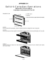
STEP #1
Remove the bottom grille from the fireplace, by removing the rear screw and sliding the rod to one side.
STEP #2
Place the blower assembly on to the two (2) studs towards the back of the base and fasten with two (2) 10-32 hex
nuts provided.
Make sure the blower is pushed to the rear as far as the slots will allow. Do not overtighten the hex nuts that secure
the blower to the base. The foam gasket should only be slightly compressed.
STEP #3
Install the variable speed/electrical box on the two studs located at the side front of the base (opposite side of air
kit, if used) and securing it with the two (2) 10-32 hex nuts provided. If studs are not present, drill and secure to side
of unit. The speed control may be installed in the junction box or located remotely.
If the speed control is to be located in the junction box, the knock out on the front of the box must be removed. The
speed control is then inserted between the cover plate and the housing of the box. Be sure to align the tabs of the
speed control with the holes that secure the cover plate to the junction box and reassemble.
If the speed control is to be located somewhere else, an electrical junction box not provided must be installed around
the control and the system must be wired in accordance with local and or national electrical codes.
STEP #4
Wire this assembly to a 120 volts power supply. Note: A licenced or qualified electrician must make the power
connection. See figure 1.
STEP #5
Feed the air deflector into the bottom and lift the air deflector up and position the vee bend into the vee frame of the
blower. See figure 2.
LINE
L1
MOTOR
ON/OFF & VARIABLE
SPEED CONTROL
BLOWER WIRING
DIAGRAM
FIGURE 1
FIGURE 2


