Page 5
CHIMNEY FRAMING DETAILS
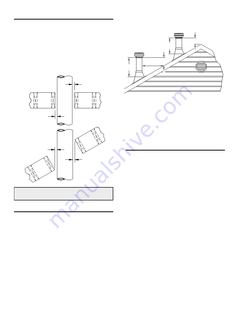
1. Plan your chimney installation carefully. Lay out
and frame in the required openings, ensuring the
specified 50mm(2") clearance to combustibles is
maintained. All openings should be square, plumb,
and in perfect alignment with each other. See figure 4.
2. For sloping roofs, ensure that the framing dimension
is measured in the horizontal plane. See figure 4.
FIGURE 4
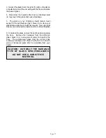
5. The use of locking bands or stainless sheet metal screws
(#6 x 3/4") should be used on all interior joints. Locking
bands must be used on all sections that make up an offset
and exterior joints.
6. Figures 6 - 9 shows the four basic types of installations most
likely to be encountered when installing a Model 640/ZC40
fireplace system.
All joist areas must be fully framed to accept a Radiation /
Dust Shield. The SS Radiation / Dust Shield must be used
at all joist levels except an open attic level. Use 1-1/2" nails
to attach it to the joists. The shield may be trimmed but must
remain 25mm (1") below or above the ceiling.
RADIATION / DUST SHIELD
3ft.
10ft.
2ft.
3ft.
2ft.
FIGURE 5
50mm(2")
50mm(2")
50mm(2")
50mm(2")
MINIMUM CLEARANCE TO COMBUSTIBLES
50mm (2")
CHIMNEY INSTALLATION INSTRUCTIONS
1. The minimum approved system height is 4.3m(14') and
the fireplace is designed to support up to 7.6m(25') of vertical
chimney. For greater heights additional supports are required
at each 7.4m(24').
2. Except for installation in one and two family dwellings,
your chimney that extends through any zone above that on
which the connected appliance is located, is to be provided
with an enclosure having a fire resistance rating equal to or
greater than that of the floor or roof assemblies through it
passes.
3. Authorities require that the chimney extend not less than
1m (3') above the highest point where it passes through the
roof of a building and not less than 609mm (2') above any
portion of the building within 10'. See figure 5.


