background image

4

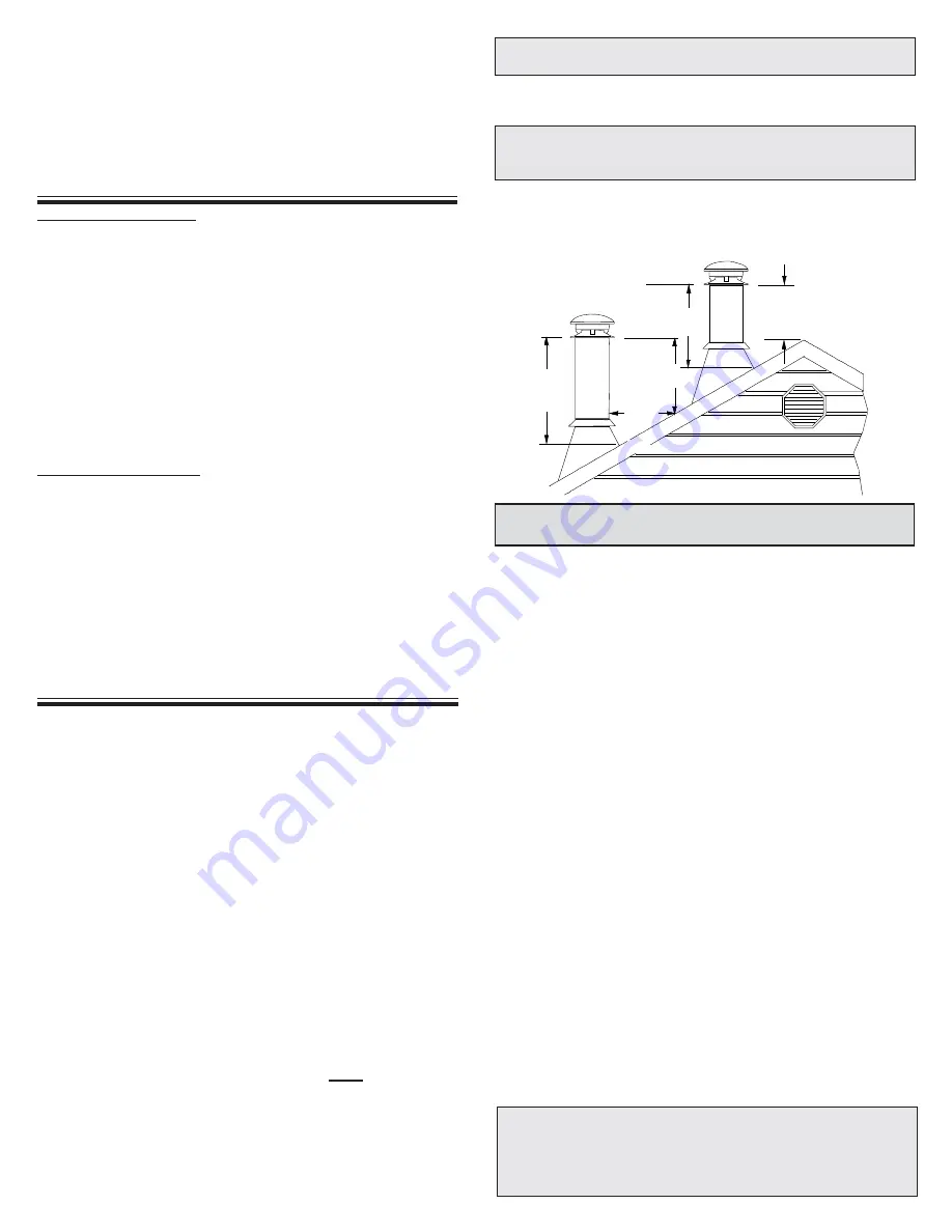
10 pds.

2 pds.

min.

3  pds.

min.

2  pds.

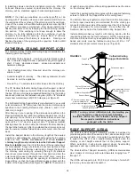
Authorities require that the chimney extend not less than 3 feet
(900 mm) above the highest point where it passes through the roof
of a building and not less than  2 feet (600 mm) above any portion
of the building within 10 feet (3 m).  See figure 1 and Chart 2.

The ideal  location for  your chimney is within the building
envelope. In cold climates, the use of external chimneys may
result in operational problems such as poor draft, excessive
condensation of combustion products and rapid accumulation of
creosote.  Under these circumstances, the installation of the
chimney within the building is strongly recommended.

If the chimney must be installed on an exterior wall it is
recommended that the chimney be enclosed below the roof line
to protect the chimney from cold outdoor temperatures, this may
help reduce condensation, creosote formation and enhance draft.
Provide an access door by the Tee Plug for chimney inspection
and cleaning.  The exterior enclosure may be insulated, maintaining
the required minimum air space clearance of 2" (50mm) to any
part of the chimney.  Consult local building codes for cold climate
applications.

Do not install the chimney directly at the outlet of the appliance.
Interconnecting smoke pipe is required unless the appliance is
specifically approved for that type of installation.

Use only with an appliance listed by a recognized testing
authority such as Underwriters Laboratories Inc., Underwriters
Laboratories of Canada, Intertek Testing Services, Warnock
Hersey or ICBO.

The flue diameter of gas or oil fired appliances should comply
with the appropriate Installation Codes such as CAN/CSA-B139
or CAN/CSA-B149 when installed in Canada, and the Installation
Codes NFPA 54, ANSI Z223.1 and NFPA 31 in the United States.

W

ARNING

:  D

O


NOT


PLACE


ANY


INSULATING


MATERIALS


OR


RUN


ANY


ELECTRICAL

WIRING


WITHIN


THE


REQUIRED


AIR


CLEARANCE


SPACE


SURROUNDING


THE


CHIMNEY

.

M

AINTAIN


A

 2" 

MINIMUM


AIR


SPACE


CLEARANCE


BETWEEN

INSULATED


CHIMNEY


SECTIONS


AND


COMBUSTIBLE


MATERIALS

.

Your CF Sentinel chimney and connecting stove pipe diameter should
be sized in accordance with the appliance manufacturer’s
recommendations.
Plan the installation of your appliance and chimney in such a way that
both your chimney and your chimney connector (stovepipe) run is as
short and straight as possible.  By having too long and / or multiple
bend installations you can reduce system draft which can affect the
operation, and or performance of your appliance and or the chimney
system.  The chimney should be located within the building as to avoid
cutting or altering load bearing members such as joists, rafters, studs,
etc.  If you have to cut or alter an existing load bearing member, special
reframing methods are required which often include doubling of
adjacent members.  If such a case arises, contact your local Building
Code Official regarding local regulations and proper installation
methods.
Before commencing the installation ensure that you obtain any
necessary building permits, and that your installation will conform with
all federal and municipal building codes requirement.

Sections of the CF Sentinel chimney which pass through accessible
areas of the building such as through closets, storage areas, occupied
spaces or any place where the surface of the chimney could be
contacted by persons or combustible materials 

must

 be enclosed in

a chase.  The chase may be fabricated using standard building
materials.  Drywall mounted on  2” x  4” studs is typically used in this
situation.   Except for installation in single and two family dwelling,
factory-built chimneys shall be enclosed with approved walls having
a fire resistance rating equal or greater than that of the floor or roof
assemblies through which they pass. The space between the outer
wall of the chimney and the enclosure shall be at least 2 inches.

TYPES OF APPLIANCES

PRE-INSTALLATION GUIDELINES

If you have a basic knowledge of carpentry and how to use hand
tools, taking on the task of installing your new venting system will
be easy.  However, it is important that these installation instructions
are followed.  If you choose to have your product professionally
installed, we recommend these products be installed by
professionals who are certified in Canada by WETT (Wood
Energy Technology Transfer) or l'APC (l'association des
professionels du chauffage) or NFI in the US.

Be sure that ladders are in good condition and always rest on a
level firm surface.

Be sure that electrically powered tools are properly grounded.

Y

OUR


CHIMNEY


HAS


BEEN


TESTED

AND


LISTED


USING

ALL


OF


THE


SUPPORTS

SHIELDS

ETC

., 

DESCRIBED


HEREIN

.

D

ELETION


OR


MODIFICATION


OF


ANY


OF


THE


REQUIRED


PARTS


OR

MATERIALS


MAY


SERIOUSLY


IMPAIR


THE


SAFETY


OF


YOUR


INSTALLATION

,

AND


VOID


THE


CERTIFICATION


AND


OR


WARRANTY


OF


THIS


CHIMNEY

.

FIGURE 1

3 ft.

min.

CANADA APPLICATIONS

Your CF Sentinel chimney has been tested per CAN/ULC-S629
as an all fuel chimney.  As such it is code approved for connection
to solid, liquid or gas fueled residential type appliances and
building heating appliances in which the maximum continuous
flue gases temperatures do not exceed 650°C (1200°F).  It has
also been tested and approved to withstand temperatures of up
to 2100°F for three thirty minutes intervals.
The installation should be in accordance with the Installation
Code  CAN/CSA-B365 (Solid-Fuel-Burning Appliances and
Equipment) and / or the National Building Code of  Canada and
Provincial Building Code, etc. should be consulted.
May also be used with specific factory-built fireplaces listed to
UL 127 and CAN/ULC-S610 when specified in the fireplace
manufacturer's installation instructions.

U.S.A. APPLICATIONS

The CF Sentinel chimney has been tested per UL-103 as "Type
HT".   As such it is code approved for connection to solid, liquid
or gas fueled residential type appliances and building heating
appliances in which the maximum continuous flue gases
temperatures do not exceed  1000°F.  It has also been tested and
approved to withstand temperatures of up to 2100°F for three ten
minutes intervals.
The installation should be in accordance with  NFPA 211 (Standard
for Chimneys, Fireplaces, Vents and Solid Fuel fired Appliances),
and / or local and regional codes such as the International
Mechanical Code and Uniform Mechanical Code, etc.

W

EAR


SAFETY


GLOVES


WHEN


HANDLING

SHEET


METAL


PARTS


WITH


SHARP


EDGES

C

ONTACT


LOCAL


BUILDING


OR


FIRE


OFFICIALS


ABOUT


RESTRICTIONS


AND

INSTALLATION


INSPECTION


IN


YOUR


AREA

.

Summary of Contents for CF Sentinel

Page 1: ...nce guide in a safe place for future reference INSTALLATION INSTRUCTIONS MAINTENANCE GUIDE Tested to Standard CAN ULC S629 UL 103 Type HT PLEASE READ ALL INSTRUCTIONS BEFORE BEGINNING YOUR INSTALLATION FAILURE TO INSTALL THIS SYSTEM IN ACCORDANCE WITH THESE INSTRUCTIONS WILL VOID THE CONDITIONS OF CERTIFICATION AND THE MANUFACTURER S WARRANTY A MAJOR CAUSE OF CHIMNEY RELATED FIRES IS FAILURE TO MA...

Page 2: ...JOISTSHIELD ATTICINSULATIONSHIELDINSTALLATION ELBOWINSTALLATION WALLSUPPORTINSTALLATION WALL BAND CATHEDRALCEILINGSUPPORTINSTALLATION ROOFSUPPORTINSTALLATION ROOFFLASHINGINSTALLATION ROOFBRACEKITINSTALLATION ROUNDTOP SPARK ARRESTER MAINTENANCEANDCLEANINGOFCHIMNEY REPLACEMENT PARTS LIST ANCHOR PLATE FOR MASONRY FIREPLACE CHART1 OFFSETCHIMNEYINSTALLATION CHART 2 CHIMNEY HEIGHT ABOVE ROOF CHART 3 CON...

Page 3: ...3 CERTIFICATIONLABELS ...

Page 4: ...the CF Sentinel chimney which pass through accessible areas of the building such as through closets storage areas occupied spaces or any place where the surface of the chimney could be contacted by persons or combustible materials must be enclosed in a chase The chase may be fabricated using standard building materials Drywall mounted on 2 x 4 studs is typically used in this situation Except for i...

Page 5: ... the top of the length Once you have assembled the lengths together a locking band must be installed With the insulation being compressed this will provide insulation to insulation contact see Figure 2 NOTE When the insulation retainers melt or volatilize during high temperature operation the compressed insulation will fill in FIGURE 2 Insulation Locking Band Locking Band Seated All Around Insulat...

Page 6: ...tove pipe run should be as short and straight as possible and secured in place with a minimum of 3 sheet metal screws per joint Generally for a wood burning appliance installation an 18 minimum clearance to combustibles must be maintained for the stove pipe NOTE The exception to this is a double wall stove pipe such as Selkirk s Model DSP which can be installed at reduced clearances to combustible...

Page 7: ... Joist Framed all 4 sides Floor Ceiling Joist Framed all 4 sides Roof Joist Framed all 4 sides Two Story Basement Installation Ceiling Support Living Space FramedEnclosure2 50mm clearancefrom chimney to combustible wall Smoke Pipe Adapter Firestop Joist Shield FIGURE10 Firestop Joist Shield Positioned into Framing from below Close Box Corners Using Tabs ChimneyLength Nail Side Flanges Securely To ...

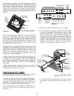
Page 8: ... Flashing Smoke Pipe Adapter RoundTop StormCollar Chimney Sections Attic Insulation Shield Ceiling Support Ceiling Joist Framed all 4 sides FIGURE13 Roof Joist Framed all 4 sides Lower Bucket FIGURE 14 Attic Insulation Shield Fully frame a level square opening all four sides for 2 50mm clearance from the outside of the chimney to the inside of the frame Place the Firestop Joist Shield JS up into t...

Page 9: ...SI into the Attic Insulation Shield See separate installation instructions FIGURE15 NOTE At the level where the chimney penetrates the air vapour barrier special attention is required Seal the vapour barrier to the Ceiling Plate of the Ceiling Support Wall Thimble or Attic Insulation Shield using an appropriate caulking compound as per the requirement of local authorities StainlessSteel SheetMetal...

Page 10: ...braces up or down as necessary DOWN IF CHIMNEY GOES THROUGH WALL as per Figure 19 20a and if it is an interior wall support installation Figure 20b 3 Nail brackets and angles to framing temporarily making sure that the base plate is level and positioned to allow for the installation of the wall plates if the chimney goes through the wall TABLE 3 Chimney Size Hole Non Combustible Framed Opening Com...

Page 11: ...nd hand tighten 4 Line up the perforated straps and wall brackets then mark position on wall for lag screws or anchors to go through both the straps and brackets 9 After checking fit secure Tee to integral basecap of base plate with a locking band Install the Tee Plug and turn the two 2 twist lugs 10 Use a non hardening high temperature sealant 500 o F to seal around the exterior portion of the ho...

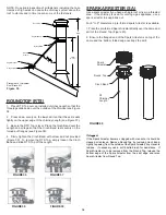
Page 12: ... 4 painted ceiling trim angles 2 short 2 long decorative sleeve smoke pipe adapter and hardware package Roof Flashing Assembly Required when the chimney pen etrates a roof Suitable lengths of chimney The chimney diameter should be sized to suit the appliance Round Top To exclude rain and or leaves into the chimney The CF Sentinel Cathedral Ceiling Support will support a total of 15feet 4 6m ofchim...

Page 13: ...loosely tighten the tabs with the screw and nut referenced in Step 2 Move the assembly to the desired height location on the pipe Firmly tighten bolt and nut to secure the band around the pipe 5 Secure URSA to the length of pipe by using four 4 1 8 x 1 2 stainless steel self tapping screws provided through the 2 securing holes found closest to the tabs on the band see Figure 24 6 The URSA is mount...

Page 14: ...tinue adding chimney lengths until the proper height is achieved See figure 30 Install the Round Top as per the instructions under the Round Top section Figure 28 The Universal Roof Brace Kit URBK will provide lateral support to the chimney above the roof line The URBK is required when the chimney extends 5 feet 1600mm or more above the roof penetration The URBK contains Telescoping Legs Support B...

Page 15: ...33 Assembly of Telescoping Legs to Support Band Flange Nut Smaller Diameter Telexcoping Leg Roof Shingles Rafter or framing structure 1 Bolt Angle Bracket 2 Lag Screws Figure 34 Securing Angle Bracket G Attach each of the telescoping legs angled end to the 2 elevator bolts on the Support Band with supplied washers and nut see Figure 33 H Attach one end of each telescoping leg assembly to each of t...

Page 16: ...nly on the turned out flanges see Figure 38 4 Firmly tighten the Cinch Band with screw and nut provided Figure 39 To remove the RTS Top simply loosen the Cinch Band and slide RTS Top off the Length FIGURE36 FIGURE37 FIGURE38 FIGURE39 RoundTop SupportBand LockingBand Angle Bracket 2 Lag screws 10 MAX 2 3rd OF HT Hose Clamp Figure 35 Placement of Universal Roof Brace Kit NOTE Do periodic inspection ...

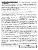
Page 17: ... professional certified chimney sweep for chimney cleaning services and advice if you have any doubts about your ability to clean your chimney system or if the task is too large If chemical cleaner is used to assist in cleaning your chimney make sure it is a product which is non corrosive Selkirk will assume no liability for damage resulting from the use of chemical cleaners It does not replace th...

Page 18: ... burn hot emit less smoke and create less creosote Un seasoned wood when burned must release water stored within the wood This cools the fire creates creosote and hampers a complete burn Be careful of wood advertised as seasoned You may want to invest in a moisture meter Signs of seasoned firewood are Dark colored wood darkens with age Cracks in the end grain radiating from the center of the log l...

Page 19: ...ace and level the Anchor Plate over the extended studs Secure using a washer and nut for each bolt 4 Check the Anchor Plate for level and allow mortar to set 5 Place the flue extension crimped end down into the opening of the Anchor Plate Place a section of chimney onto the Anchor Plate and secure to the Anchor Plate with a Locking Band and stainless steel sheet metal screws see CF Sentinel Joint ...

Page 20: ...the proper chimney diameter of your system 2 Determine the distance of the offset required by dropping a plumb bob for an accurate mea surement The offset is measured at the chim ney centre line as per the A measurement in the diagram 3 On the chart find the predetermined distance under the A column required for the 15 o elbow For greater offset use the 30 o offset chart 4 After finding the offset...

Page 21: ... roof a Roof Brace Kit is required PITCH OF ROOF DISTANCE FROM PEAK 10 Ft 9 Ft 8 Ft 7 Ft 6 Ft 5 Ft 4 Ft 3 Ft 2 Ft 1 Ft CHIMNEY HEIGHT ABOVE ROOF INCHES CHART 3 Connector Pipe Clearance below Cathedral Support 1 Identify the type of connector pipe you will be installing single wall requires 18 clearance to combustibles or Selkirk s Double Wall Stove Pipe model DSP which requires 6 clearance to comb...

Page 22: ...LLATION DATE __________________________________________________ DEALER INFO DEALER NAME _______________________________________________________ Address _____________________________________________________________ City ________________________________________________________________ Province _____________________________________________________________ TECHNICIAN INFO TECHNICIAN NAME _____________...

Reviews: