9
Smoke Pipe Adapter
Elbow
Elbow Support Band
Locking Bands
Elbow
Ceiling Joist
(Framed all 4 sides)
Floor, Ceiling Joist
(Framed all 4 sides)
Round Top
Storm Collar
Roof Flashing
Chimney Sections
Roof Joist
(Framed all 4 sides)
Elbow Support Straps
Locking Bands
Ceiling Support
Living Space
Attic Space
Attic Insulation Shield
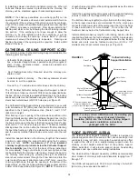
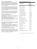
Offset (Elbow) Installation
FIGURE 16
Lower Bucket
Framed Enclosure 2" (50mm)
clearance from chimney to
combustible wall
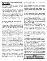
Install a Resupport Assembly on the vertical length just above the
highest elbow. Securely clamp the Support Band to the chimney
just above the locking band at the joint. Attach the Support Straps
to the Support Band assembly and nail the Support Straps to the
framing using 1-1/2” nails or #8 x 1-1/2" wood screws (2 per straps).
See Figures 17 and 18.
The weight carrying capacity of the support, which depends on
the angle of the straps, and the security of attachment is
adequate for 9 m (30') of Model CF Chimney pipe.
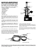
ELBOW INSTALLATION
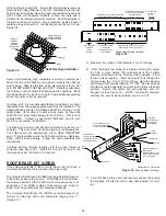
Framed Enclosure 2" (50mm)
clearance from chimney to
combustible wall
Living Space
Roof Flashing
Ceiling Support
Smoke Pipe Adapter
Round Top
Storm Collar
Floor, Ceiling Joist
(Framed all 4 sides)
Ceiling Joist
(Framed all 4 sides)
Attic Insulation Shield
Attic Space
Chimney Sections
Two Story
Main Floor Installation
Roof Joist
(Framed all 4 sides)
Lower Bucket
NOTE: To reduce cold air infiltration into the dwelling you can
install the optional Universal Shielding Insulation (SUSI)
into the Attic Insulation Shield. See separate installation
instructions.
FIGURE 15
NOTE: At the level where the chimney penetrates the air / vapour
barrier, special attention is required. Seal the vapour barrier to the
Ceiling Plate of the Ceiling Support, Wall Thimble or Attic
Insulation Shield using an appropriate caulking compound as per
the requirement of local authorities.
Stainless Steel
Sheet Metal
Screws
FIGURE 18
Two pairs (four) of 15
o
or 30
o
elbows may be used in an interior
installation to provide an offset in order to avoid cutting of joists and
to clear other obstructions.
Locking bands must be used at each joints. For added security
when forming an offset, it is required to fsten the joints using two
(2) X6 x 1/2" stainless steel sheet metal screws through the pro-
punched holes in the locking bands (see Figure 16).
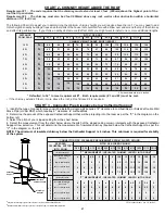
The maximum permissible angle with solid fuel CF installation is 30
degrees. Combining offsets for greater angle is not permitted. The
vertical run of chimney above an offset must be supported using an
Interior Resupport Assembly. Each Interior Resupport Assembly
will support 30 feet (9 m) of chimney and the maximum length of
chimney allowed between the elbows is 6 feet.
See Chart 1 for Offset Chimney Installation at the back of these
instructions for more information.
Never install an elbow in a joist area. Chimney sections must
pass vertically through a framed joist areas.
During installation provide supplementary support for the offset
section to avoid undue stress on connected elbows.
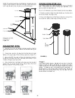
Support Band
Straps
Locate Support
Band Below
Locking Band at
Joint
Bend Straps
Over Framing,
Nail Securely
FIGURE 17
Summary of Contents for CF Sentinel
Page 3: ...3 CERTIFICATIONLABELS ...


