background image


24

Installing the Gravity Air Duct System 

1.  Remove the 7” (178 mm) knockouts in the top of the appliance. Cut the insulating wool and remove the 

inner knockouts. Solidly attach the duct adaptor to the appliance. 

2.  Always provide a minimum 2” (51 mm) clearance between the hot air duct and any combustible materials 

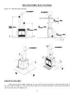
and a 6” (152 mm) clearance between any hot air outlet and the ceiling. (Figure #21) 

3.  Direct the gravity heating ducts upward or horizontally. 

Never

 direct a duct downward. 


This system must never be connected to a forced air heating system.

 If the heating system’s blower 

were to malfunction, the fireplace enclosure would overheat. Selkirk makes a system specially designed for use 
with forced air heating systems. (Figure #22) 


The dimensions recommended for the Gravity Vent Kit are the following: minimum height of 68” (1727 

mm) from the base of the fireplace to the centre of the hot air grill and a maximum of 10’ (3 m). (Figure #19) 


With the Gravity Vent Kit, you can install a finish over your chimney and fireplace. Just remove the 

upper louver, install insulated panel and cover it with whatever non-combustible finish you prefer (brick, stone, 
marble, ceramic tile, etc.). Gypsum is not an acceptable material. (Figure #20) 

WARNING: It is mandatory to install hot air gravity kit when installing cast iron front option. 

FORCED AIR KIT 


The Forced Air Kit (MAX-FAK) can be used to heat adjacent rooms or lower floor located up to 50’ 

(15.2 m) from your Selkirk Fireplace. Only 6” (15cm) flexible isolated duct can be use for this installation. 
(Figure #20) 


If the fan is installed with a rheostat, the operation is manually control. The fan can be install with the 

thermo-disc located under fireplace’s floor, it start automatically when fireplaces floor reach 120°F (50°C). In 
cooling cycle the fan stops automatically when the fireplace temperature gets under 120°F (50°C).  

The Forced Air Duct System can be installed in one of two ways 

1.  Install the flexible duct and connect it to the adaptor attached to one of the fireplace’s two side openings. 

Install the duct system leading to adjacent rooms on the lower floors. The fan can be installed anywhere in 
the house except in the chase. If the fireplace is in a small room, the central fan can be used to draw and 
redistribute excess heat throughout the house. Be careful where you install the fan, so its noise will not be a 
nuisance. The length of the duct from the fireplace to the farthest hot air grill must not exceed 50’ (15.2 m). 
A certain loss of heat is to be expected at this distance. A plastic duct may be connected to the fan’s outlet 
as long as the duct’s heat resistance is at least 250°F (121°C). Never install a plastic duct in the fireplace 
enclosure. 

2.  The duct can also be safely connected to an existing heating system. However, do not connect any hot air 

ducts to the cold air return. The hot air duct must be connected to the main duct coming out of the blower. 
Install a backflow shutter at the junction between the fireplace duct and the blower outlet duct. 

Summary of Contents for Chardonnay

Page 1: ...FABRICATED WOOD BURNING FIREPLACE INSTALLATION AND OPERATION MANUAL Keep this manual for future reference Standards ULC S610 UL 127 E P A Standards Exempt Revised June 2009 Web Site www maxfireplaces...

Page 2: ...llation 9 Masonry Chimney Installation 9 Fireplace Finish 14 USE AND SAFETY 18 Creosote 19 Chimney Fire Safety Procedures 19 MAINTENANCE 19 Replacing Glass 20 Replacing Chardonnay Refractory Brick 20...

Page 3: ...all the instructions contained herein and keep this manual handy so you may refer to it whenever necessary Before starting to install the fireplace consult local authorities to obtain a construction p...

Page 4: ...cur No other device must be added to the chimney connected to the fireplace Choose the best location for your fireplace based on the position of the doors and windows Provide for the positioning of th...

Page 5: ...5 Figure 2 Various Fireplace Locations Figure 3 Possible Chimney Configurations Figure 4 Fireplace Framing...

Page 6: ...s such as wood or plywood or any other hard sturdy surface 4 A 48 x 16 1220 mm x 407 mm minimum hearth extension made of non combustible material is required The extension can be installed below the b...

Page 7: ...nsulated flexible duct and attach it to the inlet grill with aluminum duct tape or 19 mm metal screws 13 On the lower left side of the fireplace remove the metal piece blocking the air intake Cut the...

Page 8: ...d fireplaces and ANSI Z233 1 with regards to the National Gas Code ATTENTION ALWAYS OPEN THE CHIMNEY DAMPER TO ITS MAXIMUM POSITION WHEN USING A DECORATIVE GAS APPLIANCE THIS FIREPLACE HAS NOT BEEN TE...

Page 9: ...at all points a minimum clearance of 2 51 mm separates the chimney and any combustible materials NOTE Since May 1997 whatever the type of fireplace or building safety standards require that the firep...

Page 10: ...liner 6 Add a small liner section to the liner elbow which will allow the liner to extend at least 12 measured at the top of the liner from the masonry chimney 7 Seal the opening around the liner wit...

Page 11: ...11 Figure 7 Minimum Chimney Height...

Page 12: ...12 Figure 8 Masonry Chimney Installation...

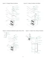
Page 13: ...13 Figure 10 Straight Chimney Installation Figure 11 Chimney Installation with Elbows Figure 12 Chimney Installation through an Exterior Wall Figure 13 Isolated Chase Chimney Installation...

Page 14: ...tail B 5 In all cases the enclosure must reach at least 84 2133 in height from the base of the fireplace Do not insert insulation in the chimney enclosure Figure 15 6 It is possible to enclose the top...

Page 15: ...15 Figure 15 Chimney Enclosure Chimney enclosure USA and Canada Chimney enclosure Canada only...

Page 16: ...16 Figure 16a Mantel Positioning...

Page 17: ...17 Figure 16b Combustible materials positioning A 48 in B Radius of 84 in C 84 in Min...

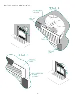
Page 18: ...18 Figure 17 Installation of Fireplace Facing...

Page 19: ...can contain Do not burn garbage painted wood or wood that has been exposed to salt water 9 Always have minimum of 1 accumulation of ashes at the bottom of the fireplace The grate may deform if no ashe...

Page 20: ...fireplace have it inspected by the Fire Department MAINTENANCE 1 Clean metal trim with soapy water and a soft cloth Do not use any metal polish or abrasives 2 Keep the glass clean Dirty windows will m...

Page 21: ...ove the front refractory brick VA2071 5 2 Remove the upper deflector PL60004 holding the side wall stones in place 3 Remove the log support VA2070 by pulling on it until it comes free 4 Remove the flo...

Page 22: ...air supply 5 Any type of fan range hood or bathroom exhaust fan that draws air outside can create negative pressure Shut off the fan and or open a window near the fireplace to solve this problem 6 We...

Page 23: ...VITY VENT KIT The Gravity Vent Kit MAX GVK may be used to heat rooms located above behind and either side of the room where the fireplace is located Note that if the hot air outlets are located at var...

Page 24: ...or located up to 50 15 2 m from your Selkirk Fireplace Only 6 15cm flexible isolated duct can be use for this installation Figure 20 If the fan is installed with a rheostat the operation is manually c...

Page 25: ...pplicable National Building Code standards Install the rheostat close to the fireplace so it can be easily closed whenever you must open the fireplace doors If the fan is running the smoke will be dra...

Page 26: ...26...

Page 27: ...27...

Page 28: ...28...

Reviews: