5
2"
(50mm)
Min
2" (50mm)
Min
2" (50mm) Min
2" (50mm)
Min
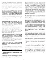
14 x 14
355 x 355
14
3
/
8
x 14
3
/
8
365 x 365
14
3
/
8
x 14
3
/
8
365 x 365
14
3
/
8
x 14
3
/
8
365 x 365
14
3
/
8
x 14
3
/
8
365 x 365
6"
(150mm)
7"
(175mm)
8"
(200mm)
15 x 15
380 x 380
16 x 16
14
3
/
8
x 14
3
/
8
365 x 365
365 x 365
14
3
/
8
x 14
3
/
8
405 x 405
mm
mm
mm
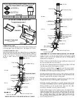
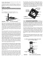
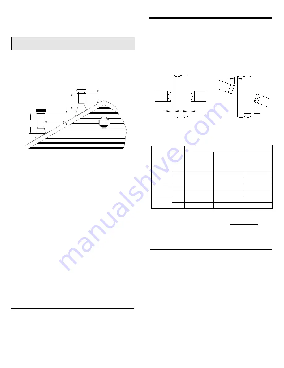
Authorities require that the chimney extend not less than 3 ft
(900 mm) above the highest point where it passes through the
roof of a building and not less than 2 ft (600 mm) above any
portion of the building within 10 ft (3m). See Figure 1 and Chart
2 on page 20 of these instructions.
3 ft. (900mm)
min.
3 ft. (900mm)
min.
2 ft.
(600mm)
2 ft.
(600mm)
10 ft.
(3m)
The use of Locking Bands at all chimney joints is recommended for
added safety and stability when exposed to high winds and as a
precaution against accidental unlocking of lengths when the system
is inspected and swept.
Do not install the chimney directly at the outlet of the appliance.
Interconnecting stove pipe is required unless the appliance is specifi-
cally approved for that type of installation.
Use only with an appliance listed by a recognized testing authority
such as CSA, Underwriters Laboratories Inc., Underwriters Labora-
tories of Canada or Intertek Testing Services/Warnock Hersey.
Do not mix and match with other manufacturer's products. Use only
Selkirk's Models JM/ALT listed components.
TOOLS
Your model JM/ALT chimney system is designed for installation
using standard building materials and procedures. The following
tools/equipment may be required as well as some others depending
on the location and structure in which the chimney is to be installed:
FIGURE 1
-Screwdrivers and pliers
-Plumb line and level
-Square
-Keyhole saw or power jig saw
-Caulking gun
-Safety gloves
-Safety goggles
-Hammer and nails
-Tin snips
-Tape measure
WEAR SAFETY GLOVES WHEN HANDLING
SHEET METAL PARTS WITH SHARP EDGES
CHIMNEY SIZING:
In order to achieve safe, optimum performance of the appliance,
service life of the chimney, the chimney must be sized correctly for
the connected appliance. In general, the chimney flue should be the
same size as the appliance flue outlet. The installation should be
done in accordance with the applicable installation codes (eg. CAN/
CSA B149, CAN/CSA B139, NFPA 54 and NFPA 31) and appliance
manufacturer instructions. Plan the installation of your appliance
and chimney in such a way that both your chimney and flue pipe runs
are as short and straight as possible. By having too long and/or
multiple bend installations you can reduce the system draft which
can affect the operation, and/or performance of your appliance and/
or chimney system.
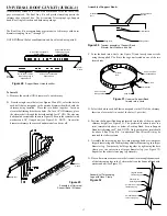
Plan your installation carefully. If possible, position the stove so
that the flue outlet is centered between joists or rafters. Drop a plumb
line to the center of the flue outlet and mark this center point on the
ceiling. Lay out and frame in all openings ensuring the specified 2" (50
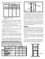
mm) clearance to combustibles is maintained. Refer to Table 1 and
applicable Tables for framing dimensions and mark the appropriate
cutting lines around the center point. All openings should be square,
plumb and in perfect alignment with each other (see figure 2).
For sloping roofs (cathedral/vaulted ceiling), ensure that the framing
dimension is measured in the horizontal plane (see figure 3).
FRAMING DETAILS
* The clearance to combustibles obtained with a correctly installed
Decorator Ceiling Support or Wall Thimble in the framed opening
specified has been tested.
The 2" clearance does not apply at these
locations.
When cutting the inside "finished" surface of your wall or
ceiling cut a
"round hole"
to the framing dimension in Table 1.
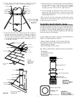
To complete a proper Decorator Ceiling Support installation, the
following parts may be required:
-Decorator Ceiling Support (DCS): Required when supporting a
chimney through a flat level ceiling.
- Stove Pipe Adaptor (ASE): Transition from the chimney to flue pipe.
- Attic Insulation Shield (AIS): Required where a chimney passes
from a lower living space into an upper living or an attic space.
- Universal Shielding Insulation (JUSI): To reduce cold air infiltra-
tion into the dwelling when installed in conjunction with the Attic
Insulation Shield.
- Rafter Radiation Shield (RRS): Required when the chimney is
enclosed immediately below the roof line.
- Roof Flashing Assembly (Including Storm Collar): Required when
the chimney penetrates a roof.
INSTALLATION PROCEDURES
FIGURE 3
Typical Roof
Joist Framing
FIGURE 2
Typical Joist
Framing
*Decorator
Ceiling
Support
*Wall
(Support)
Thimble
Framing Dimensions Table
All Other
Framing
Chimney Flue
Diameter
TABLE 1
DECORATOR CEILING SUPPORT (DCS)
in.
in.
in.

