6
The crimped end (stub) of the Stove Pipe Adaptor is intended to fit
inside of the flue pipe from a solid fuel appliance, thus preventing
condensate drips at the chimney connection. Install inter-connecting
flue pipe following the appliance manufacturer's installation
instructions and appropriate building code requirements keeping
in mind that the flue pipe run should be as short and straight
as practicable. Generally, for a wood burning appliance installation,
an 18" minimum clearance to combustibles must be maintained for
a single wall flue pipe. The exception to this is a double wall
stove pipe, such as Selkirk's
Model DSP
which can be installed
at reduced clearances of 6" to combustibles. See separate installation
instructions for more details.
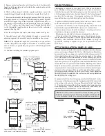
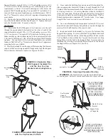
Ceiling Support. Lower the assembly down into the Decorator Ceiling
Support ensuring that the stovepipe adaptor sleeve is protruding
through the support and into the living space (see Figure 5). Do not
install an elbow in the Ceiling Support. Make sure that the male
coupler of the insulated Chimney Length is pointing upwards as
indicated by the arrow on the chimney label.
Install additional chimney sections and lock together by turning
clockwise until the two sections lock together tightly. Even though
Locking Bands are optional, it is always recommended to install a
locking band to secure the chimney sections. Continue adding
chimney lengths until a height of about 2ft. below the next ceiling
level is achieved.
NOTE: The Decorator Ceiling Support cannot be used when the
chimney terminates in a room with a suspended ceiling.
When false ceilings are encountered, use a Cathedral Ceiling Support
to extend into the room below the finished ceiling. The floor/ceiling
joist must be framed on all 4 sides. The box must extend a minimum
of 1" below the suspended ceiling. The chimney length is to protrude
a minimum of 3" below the support and the trim angles must be
installed.
Chimney Length
Stove Pipe Adaptor
(ASE)
Decorator
Ceiling Support
FIGURE 5
The SuperVent/SuperPro Decorator Ceiling Support will support
up to 50 feet of chimney sections, all of which must be installed above
the support. Figures 4 & 10 show the 2 most common types of Ceiling
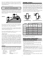
Support Installation. Frame (on all 4 sides) a level square opening to
the dimensions specified in the Framing Dimension Table 1.
Slide the Trim Ring onto the Decorator Ceiling Support and slide the
assembly into the framed opening from below. Ensure that the finishing
ring is flush with the underside of the finished ceiling and the assembly
is level and plumb. Secure the ceiling support in place using at least
three (3) 8-penny (2-1/2") nails through each of the 4 straps or through
the 12 prepunched holes in the support. You may substitute in lieu of
nails 12 - #8 x 2" wood screws.
- 15
o
or 30
o
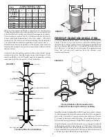
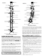
Elbow Kit: To avoid cutting of joists and clear other
obstructions. Kit includes: 2 Elbows, 1 Offset Support and 4 Locking
Bands.
- Rain Cap: Standard or Deluxe model.
Single Story Installation
Attic Space
Ventilated Flashing
Stove Pipe Adaptor
Rain Cap
Storm Collar
Chimney Sections
Attic Insulation Shield
Decorator
Ceiling Support
Ceiling Joist
(Framed all 4 sides)
FIGURE 4
Roof Joist
(Framed all 4 sides)
STOVE PIPE ADAPTOR (ASE)
The Stove Pipe Adaptor (ASE) is installed by twist-locking it into the
bottom end (female end) of the first Chimney Section that enters the
ADJUSTABLE LENGTH (AL)
An Adjustable Length (AL) is installed between other components to
establish an exact finished length, where a standard length can not be utilized.
The AL has an overall length of 12” and has an installed length that adjusts
from 2” to 9-1/2”.
The Adjustable Length is available in diameters of 5” to 8”.
The Adjustable Length must be installed above a fixed length - they cannot
be installed immediately above a support, tee or elbow.
The Adjustable Length slides over the male end of an adjoining straight
length. However, to allow engagement it is necessary to remove some of the
insulation from the inlet end of the Adjustable Length.
To install:
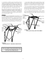
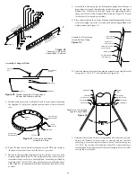
1. Determine (measure) the finished (installed) length of chimney needed
(DIM “A”) and add 2.25” to the measurement (See Fig. 6).
Note:
To facilitate installation, it is recommended that the Adjustable
Length be attached and secured to the lower adjoining segment before it is
installed in the system.
4. Measure the distance (Dim “B”) from that line to the edge of the Adjust-
able Length and add 1”. This is the “overlap” distance. On the adjoining
standard length, measure up from the male coupler, the “overlap” distance
and mark a reference line. Make sure the location of the reference line is
measured from the standard length’s male (coupler) end (See Fig 7).
3. From the male end, measure up the distance Dim “A” + 2.25” and mark
a line on the Adjustable Length (See Fig. 7).
2. Remove the Adjustable Length from the packaging carton and set it with
the male end (coupler end) of the Adjustable Length down to prevent
insulation from spilling out (See Fig. 7).

