background image

8

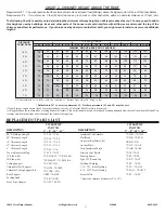
 X         X         X         X         X       X         X

 X         X         X         X         X       X         X

 X         X          X

5”       6”        7”        8”     10”    12”      14”

and install the supplied locking band.

Install the remaining offset elbow to return the chimney back to the verti-
cal position.  Again secure in place with the supplied locking band.  *Locking
bands and/or stainless steel sheet  metal screws can be utilised with a
maximum length of 12.70mm (1/2”) only on all chimney joints forming an
offset.

During installation provide supplementary support for the offset section
to avoid undue stress on connected elbows.

Install an Elbow Support on the vertical length just above the highest
elbow.  Securely clamp the support band to the chimney length just above
the locking band at the joint.  Attach the support straps to the support
band assembly and nail them to the framing using 1-1/2” nails or #8 x 1-
1/2” wood screws (2 per straps) as per Figure 13.

Never install an elbow in a joist area.  Chimney sections must pass
vertically through framed joist areas.

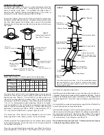
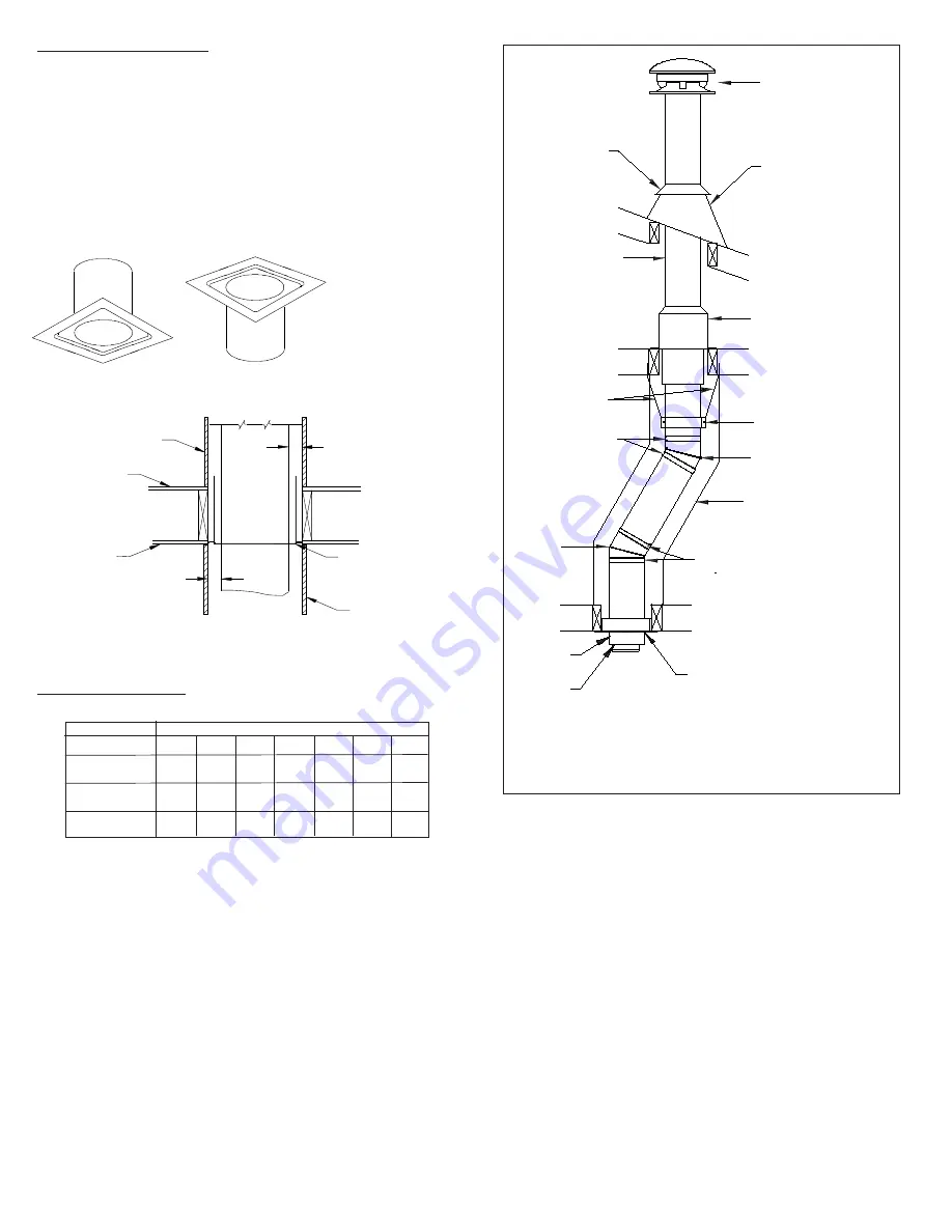
ELBOW INSTALLATION

Elbow Kits (2 elbows, 1 offset support and 4 locking bands).

FIGURE 13

Attic Insulation Shield

Storm Collar

Elbow

Locking Bands

Intermediate/Elbow
Support Straps

Locking Bands

Elbow

Ceiling Support

Roof Flashing

If the offset length is more than 1.2m (4’), an intermediate support
must be employed at 1.2m (4’) intervals.  Maximum offset length
4.8 m (16’), the intermediate support must be used in conjunction
with an offset support.

Round Top

One pair only of (two) 15 or 30 or 45 degree elbows may be used to
provide an offset in order to avoid cutting of joists and to clear other
obstructions (see Table 3).  The vertical run of chimney above an
offset must be supported with an elbow support.  Each elbow support
will support 10m (30’) of chimney.  If the offset length is more than
1.2m (4’), an intermediate support  (plumbing straps not supplied)
must be installed at 1.2m (4’) intervals in conjunction with an offset
support.  Maximum offset length is 4.8m (16’).  See the Offset Chart for
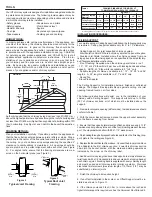
assistance in selecting your offset.  NOTE: Large diameters (10” to
14”) may combine elbow kits for a greater angle up to 45°.

15° Elbow Kit

30° Elbow Kit

45° Elbow Kit

MODEL UT

Framed Enclosure 2”
(50mm) clearance from
chimney to combustible
wall

Elbow Support Band

Roof Joist
(Framed all 4 sides)

Chimney Section

Lower
Bucket

Stove Pipe
Adapter

Floor, Ceiling Joist
(Framed all 4 sides)

Table 3

The female end of the elbows are not 

lanced

 in order to ensure

proper alignment of the chimney system can be maintained.

FIRESTOP JOIST SHIELD

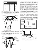
A Firestop Joist Shield  is for use in vertical enclosures where the
chimney passes through a floor / ceiling opening, from one living
space to another living space.  It is installed from either above or
below the joist.  Nail the Firestop Joist Shield using 1-1/2” common or
spiral nails, into the framed opening outlined in Table 1.

Firestop/Joist Shield (JS)
Used With UT Chimney

Enclosure
(Drywall, Plywood, etc.)

Ceiling

Minimum Clearance
2” Air Space from
Combustibles

Fire Stop/Joist Shield (JS)
Used With UT Chimney
Pipe

Floor

Enclosure
(Drywall, Plywood, etc.)

Minimum Clearance
2” Air Space from
Combustibles

Fire Stop/Joist Shield (JS)
Used With UT Chimney Pipe

FIG. 12

UT

Chimney

Pipe

FIG. 11

Enclose the chimney below the Fire Stop Joist Shield to prevent any
accidental contact with the chimney. To prevent blown-in attic insula-
tion from falling against the chimney, either use an Attic Insulation
Shield (AIS) or a full enclosure in the attic. See Section on Attic Insula-
tion Shield.

Install and position the insulated elbow on the vertical chimney length
in the required direction.  Fasten the elbow to the chimney length with
the supplied locking band.

Place the required offset chimney length(s) (see Offset Chart for ap-
propriate length(s)) on the elbow.  Turn it clockwise to lock it in place

Summary of Contents for ULTRA-TEMP UT

Page 1: ...future reference INSTALLATION INSTRUCTIONS MAINTENANCE GUIDE CANADA ONLY Tested to Standard CAN ULC S604 ULC ORD C959 PLEASE READ ALL INSTRUCTIONS BEFORE BEGINNING YOUR INSTALLATION FAILURE TO INSTALL THIS SYSTEM IN ACCORDANCE WITH THESE INSTRUCTIONS WILL VOID THE CONDITIONS OF CERTIFICATION AND THE MANUFACTURER S WARRANTY A MAJOR CAUSE OF VENT RELATED FIRES IS FAILURE TO MAINTAIN REQUIRED CLEARAN...

Page 2: ...NG FRAMINGDETAILS CEILINGSUPPORT ADJUSTABLELENGTH ATTICINSULATIONSHIELD FIRESTOPJOISTSHIELD ELBOWINSTALLATION ADJUSTABLEWALLSUPPORT WALLBAND CATHEDRALCEILINGSUPPORT ROOFSUPPORT ROOFFLASHING UNIVERSALROOFBRACEKIT ROUND TOP AND SPARK ARRESTER STOVEPIPEADAPTER ANCHORPLATE CHIMNEYOPERATIONANDMAINTENANCE OFFSETCHART CHIMNEYCHARTABOVEROOF REPLACEMENTPARTSLIST PRODUCTANDINSTALLATIONINFORMATION TABLEOFCON...

Page 3: ...3 CERTIFICATIONLABELS ...

Page 4: ...they pass The minimum airspace clearance between the outer wall of the chimney and the enclosure shall be at least 2 inches Be sure that electrically powered tools are properly grounded If you are knowledgeable in carpentry and mechanically inclined you can take on the task of installing your new venting system It is impor tant that all pertaining installation instructions and local codes are foll...

Page 5: ...ystem Attic Insulation Shield Where a chimney enters an open attic space Firestop Joist Shield Installed where the chimney passes from one living space to another living space or as specified in the listed factory built fireplace installation instructions Figure3 Typical Roof Joist Framing Figure2 Typical Joist Framing FRAMING DIMENSIONS FOR MODEL UT TO MAINTAIN 2 INCH AIR SPACE CLEARANCE Chimney ...

Page 6: ...at the Adjustable Length be attached and secured to the lower adjoining segment before it is installed in the system 8 Seal the overlap seam and screws with silicone sealant See Fig 8b 7 Re orient the assembly to the upright position Male Coupler Up and apply pressure to compress the adjoining segments together until the overlapped edge of the Adjustable Length extends down to the reference line m...

Page 7: ...pening all four sides controls vertical and horizontal spread of any fire external to the chimney ATTICINSULATIONSHIELD The function of the Attic Insulation Shield or a complete enclosure is to keep insulation from coming into contact with the chimney The height of the Attic Insulation Shield is to meet the insulation level requirement of the National Building Code Where height restrictions will n...

Page 8: ...bing straps not supplied must be installed at 1 2m 4 intervals in conjunction with an offset support Maximum offset length is 4 8m 16 See the Offset Chart for assistance in selecting your offset NOTE Large diameters 10 to 14 may combine elbow kits for a greater angle up to 45 15 Elbow Kit 30 Elbow Kit 45 Elbow Kit MODEL UT Framed Enclosure 2 50mm clearance from chimney to combustible wall Elbow Su...

Page 9: ...talled It is desirable to fully enclose an exterior chimney with minimum of 2 air space clearance to reduce creosote buildup and to promote draft The framing dimensions for the Wall Support are ilustrated in Fig 15 and Table 4 The following steps will assist you in the installation of the Adjustable Wall Support Figure 16 shows a typical Wall Support installation through a combustible wall Through...

Page 10: ...ar of Support Plate Pre Punched Holes of Support Bracket Slot for Tee Cap Bracket Flange Up FIG 18 FRONTVIEW OFWALLSUPPORTASSEMBLY Support Plate 6 Ensure that the Wall Support is level and secure to the wall through the pre punched holes located on the sides of each of the wall support brackets using 8 14 x 1 1 2 hex head lag screws or 10 x 1 1 2 wood screws You can drill 5 32 pilot holes for the ...

Page 11: ...tening the support band with the bolt and nut Secure the band to the chimney outer casing by screwing four stainless steel sheet metal screws through the support band and into the outer casing Lower the chimney length down through the opening in the bottom of the support box so that the Support Band makes contact with the bottom of the Support Box see Figure 24 Cathedral Ceiling Support w 4 painte...

Page 12: ...dditional chimney sections and lock together by turning clock wise until the two sections lock together tightly Locking bands must be used at all joints Continue in this manner until the required height above the roof is achieved Chimney sections installed below the Cathedral Support are locked together from below by turning counter clockwise until tightly locked together with each joint being sec...

Page 13: ...e 28 Apply a non hardening high temperature silicone caulking just above the top of the flashing cone where it meets the chimney casing Slide the Storm Collar through the applied caulking and place into its final position to ensure a waterproof joint Apply additional caulking above the Storm Collar as required The HDURBK will provide lateral support to the chimney above the roof line The HDURBK is...

Page 14: ... bolts and attach the top portion of each of the telescoping legs to the 2 elevator bolts on the Support Band with washers and nut see Figure 34 Leg can be bent at an angle using the claw of a hammer H Attach the other end of each telescoping leg assembly to an Angle Bracket using one 1 1 4 20 X 1 bolt and nut see Figure 35 Preparation of Telescoping Legs F Assemble the telescoping tubes by insert...

Page 15: ... pipe 2 Press down evenly on lower skirt until it contacts upper end of pipe 3 Tighten screw on collar to expand lower end and clamp to inside of pipe Keep tightening screw until collar is expanded and fully tight SPARK ARRESTER Part No SA For 6 to 8 diameters a pre formed Spark Arrester is available See separate instructions packaged with the Spark Arrester Spark Arrester To Install 1 Place the p...

Page 16: ...ect in chimney flue and on termination parts causing reduced flow of gases through the chimney Check top weekly for excessive accumulation of these normal combustion products and clean as necessary If the spark arrester becomes clogged with creosote it should be cleaned or replaced 4 Always secure all single wall flue pipe joints with a minimum of 3 screws 5 Obtain proper attachment parts for the ...

Page 17: ...ou in selecting the proper combination of elbow angle and chimney length s that will provide the necessary degree of offset within an available height 1 Select the column with the proper chimney diameter of your system 2 Determine the distance of the offset required by dropping a plumb line for an accurate measure ment The offset is measured at the chimney cen tre line as per the A Offset measurem...

Page 18: ... and other parts of the house roof could interfere with airflow over and around the top of the chimney and affect its performance If you think a nearby obstacle could affect draft you might want to install one or more additional lengths CHART 2 CHIMNEY HEIGHT ABOVE THE ROOF DISTANCE FROM PEAK 10 Ft 9 Ft 8 Ft 7 Ft 6 Ft 5 Ft 4 Ft 3 Ft 2 Ft 1 Ft CHIMNEY HEIGHT ABOVE ROOF INCHES PITCH OF ROOF Defaulte...

Page 19: ..._______________________________________________ DEALER INFO DEALER NAME _______________________________________________________ Address _____________________________________________________________ City ________________________________________________________________ Province _____________________________________________________________ TECHNICIAN INFO TECHNICIAN NAME _____________________________...

Reviews: