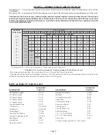
Page 10
1
5
8
7
6
4
3
2
9
10
1
2
6
4
5
3
78
91
0
11
11
3”
ROOF SUPPORT
5. Using the bent chimney plate as a template, drill 3/32" holes in
the outer casing of the chimney (do not penetrate more than 12
mm (1/2'’) into the chimney). Attach the plate with the small
sheet metal screws provided.
6. Install the second plate in a similar manner on the opposite
side of the chimney length.
The following instructions will assist you in the installation of
your chimney with a Roof Support. This support will hold up to
9.0 m (30') of chimney of which 6.0 m (20') may be suspended
beneath it.
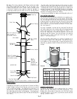
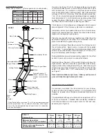
Figure 18
Figure 19
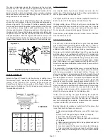
ROOF FLASHING:
Ensure that you have the proper roof flashing by checking your
roof pitch using a level and two rulers (see Figure 20) or by
using a roof pitch card.
12” Ruler
Level
Roof Pitch is 3/12
Figure 21
Figure 20
Flashing
Storm Collar
Roof Support
50mm (2”) min.
clearance
Insulated Chimney
Length
Shingles
Nails
Flashing
Framed Opening
Chimney Plate
Carriage Bolt
50mm (2”) min.
clearance
Chimney length
Bend to fit curve of
chimney
Roof Bracket
Large wood screws provided
Small sheet metal
screws (provided)
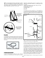
1. Frame a rectangular roof opening to provide a 50mm (2") mini-
mum clearance from combustible materials (See Figure 18).
2. Bend both chimney plates at the vertical slots to fit the outside
curvature of the chimney length (Figure 18).
7. Attach the Roof Brackets to the chimney plates. Centre the
assembly in the roof opening, ensuring that a 2” clearance to
combustible is maintained.
8. Adjust Roof Brackets to the roof pitch and tighten nuts. Attach
to the roof with six (6) large wood screws per bracket
with the inner-most screws going into the rafters or headers
(See Figure 18 & 19).
9. Additional chimney lengths above the support are simply
stacked on and locked with a 1/8 clockwise turn.
10. Locking Bands must be used on all exterior joints.
11. Finish the chimney to its required height. If the chimney
extends 1.5 m (5') or more above the roof, a Universal Roof
Brace Kit is required (see Figure 22).
3. Determine the chimney plate position on the chimney casing
(See Figure 19).
4. Install two (2) carriage bolts per chimney plate in the square
holes.
position by tightening the support band with the bolt and nut.
Secure the band to the chimney outer casing by screwing four
stainless steel sheet metal screws through the support band
and into the outer casing. Lower the chimney length down through
the opening in the bottom of the support box, so that the Support
Band makes contact with the bottom of the Support Box (see
Figure 17).
Install additional chimney sections and lock together by turning
clockwise until the two sections lock together tightly. Locking
bands must be used at all joints. Continue in this manner until
the required height above the roof is achieved.
Chimney sections installed below the Cathedral Support are
locked together from below by turning counter-clockwise until
tightly locked together with each joint being secured by locking
bands which are provided. Do not offset the chimney below the
Cathedral Support.
Roof
Apply a bead of
silicone caulking
along the seam
where the plate
meets the cone.
Apply a bead of
silicone caulking
along the back
seam of the
cone

