Page 4
2"
(50mm)
Min
2"
(50mm)
Min
2" (50mm)
Min
2"
(50mm)
Min
1-1/2”
4-1/8”
3”
INSTALLATION PROCEDURES:
CEILING SUPPORT
To complete a proper Ceiling Support installation, the following
parts may be required.
- Ceiling Support: For joist supported chimney system.
- Attic Insulation Shield: Where a chimney enters an open attic
space.
- Firestop Joist Shield: Installed where the chimney passes from
one living space to another living space or as specified in the
listed factory-built fireplace installation instructions.
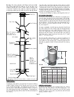
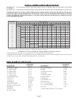
Authority require that the chimney extend not less than 3ft (900
mm ) above the highest point where it passes through the roof of
a building and not less than 2ft (600 mm) higher than any portion
of a building within 10ft (3m) horizontally. See Figure 1 and Chart
2 in the back of these instructions.
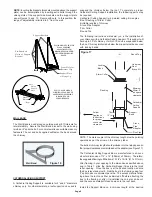
FRAMING DETAILS:
Plan your installation carefully. If possible, position the appliance
so that the flue outlet is centered between joists, rafters or studs.
Drop a plumb line to the center of the flue outlet and mark this
center point on the ceiling. Lay out and frame all openings
ensuring the specified 2” clearance to combustibles is main-
tained. All openings should be square, plumb and in perfect
alignment with each other (see Figure 2). For angled roofs, en-
sure that the framing dimensions are measured on the horizon-
tal plane (see Figure 3).
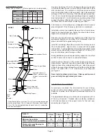
FRAMING DIMENSIONS FOR MODEL UT
TO MAINTAIN 2 INCH AIR SPACE CLEARANCE
MODEL UT
Chimney Inside
Diameter:
All other framing*
Ceiling Support*
*All framing dimensions may be up to 1/2” more, but not less than the above values.
Table 1
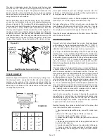
The following instructions will assist you in the installation of your
chimney with a Ceiling Support. This support will hold up to 15.25m
(50’) of chimney sections, all of which must be installed above the
support.
1. Frame a level square opening (all four sides). Inside dimen-
sions should conform to Table 1.
2. With the Lower Bucket removed, place the upper bucket
assembly into the framed opening from below.
3. Ensure that the support plate is level and flush and drive one nail,
1-1/2” common or spiral, part way into each of the four (4) nailing
areas of the support. You may substitute nails with #8 x 1-1/2” wood
screws.
4. Finish nailing through all prepunched holes (12 nails total) and
fasten the finishing (support) plate to the ceiling (see Figure 4).
5. Replace the Bucket Section from above. Connect the proper
sized Stove Pipe Adapter to the first chimney length. Lower this
chimney section down into the bucket section, with the male end
pointing upwards as indicated by the arrow on the chimney label.
6. Additional chimney lengths above the support are simply
stacked on, twist locked with a 1/8 clockwise turn and secured
with a locking band at each chimney joint. A locking band is
supplied with every chimney length and must be used on all
chimney joints, interior or exterior. Stainless steel sheet metal
screws (maximum length of 12.70mm (1/2”) may be substituted
on interior joints.
7. Finish the chimney to its required height.
8. If an offset is installed in the system, an Offset Support must be
installed as shown in Figure 7.
9. If the chimney extends 5 feet (1.5 m ) or more above the roof,
additional lateral support is required, such as the Universal Roof
Brace Kit.
3 ft.
(900mm)
min.
2 ft.
(600mm)
10 ft.
(3m)
2ft.
(600mm)
3 ft. (900mm)
min.
FIGURE 1
- Roof Flashing: Required when the chimney penetrates a roof.
- 15° , 30° or 45° Elbow Kits (2 per box with locking bands and
elbow support).
- Suitable lengths of chimney: Available in 6”, 12”, 18”, 24” and
36” lengths. A 48” length is available in 6” and 8” only.
- Round Top
- Stove Pipe Adapter
Chimney Length
Lower Bucket
Upper Bucket
The Ceiling Support is intended for installation below a finished
or unfinished ceiling.
Figure 4
Cathedral Support
Support Plate
Stove Pipe Adapter
Figure 3
Typical Roof Joist
Framing
Figure 2
Typical Joist Framing
5” 6” 7” 8”
10 1/4”
12 1/4”
11”
11 1/4”
N/A
13”
12 1/4”
N/A
14”
10 1/4”
12 1/4”
12”

