Page 5
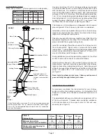
280 x 280 305 x 305 330 x 330 356 x 356
A
B
C
D
“A” DIM.
“B” DIM.
“C” DIM.
“D” DIM.
“E” DIM.
E
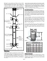
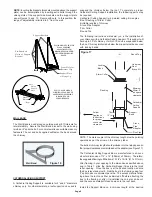
FIGURE 5
Ceiling Support
- Together with a fully framed opening (all four sides) it controls
vertical and horizontal spread of any fire external to the chimney.
- It stabilizes the chimney in the framed opening and defines and
maintains the required two inch AIR SPACE clearance to combustibles.
- It prevents heat losses from the dwelling by blocking vertical air
circulation in the space around the chimney.
- It helps provide stability for chimney extending above the roof.
ATTIC INSULATION SHIELD
The function of the Attic Insulation Shield (or a complete enclo-
sure) is to keep insulation from coming into contact with the chim-
ney. Where height restrictions will not permit the use of the Attic
Insulation Shield, an enclosure from the attic joist to the roof joist
will be sufficient. All chimney enclosures must maintain the re-
quired minimum air space clearance of 50mm (2”) to the chim-
ney (see Figure 5).
For proper installation, the attic opening should be fully framed
at 2 inches clearance to the chimney pipe with framing material
of the same dimension as the ceiling joists as per Table 2. The
tabs on the base plate of the AIS are inserted in the framed
opening around the chimney. Nail the AIS base to the framing
dimensions with at least 2 nails per side using 2d (1”) spiral
nails or 1” x #8 wood screws.
The Attic Insulation Shield allows for a depth of insulation of 10
inches plus the depth of the ceiling joists. If insulation is blown
in and adheres to the chimney pipe, it should be brushed off to
eliminate any possible contact of this material with the chimney
surface.
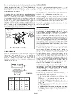
FIRESTOP JOIST SHIELD
A Firestop Joist Shield must be installed where the chimney
passes from one living space to another living space. It is
installed from either above or below the joist. Nail the Firestop
Joist Shield using 1-1/2” common or spiral nails, into the framed
opening outlined in Table 1.
Bucket Section
Floor, Ceiling Joist
(Framed all 4 sides)
LIVING SPACE
*Follow Appliance instructions for proper clearance. If clearance is not given, use
460mm (18”) min.
*Stove Pipe Adapter
Framed
Enclosure
2” (50mm)
clearance from
chimney to
combustible wall
Chimney Lengths
50mm (2”) minimum air
space clearance to
combustible material
ATTIC SPACE
Attic Insulation
Shield
50mm (2”) minimum air
space cleance to
combustible material
Round Top
Ceiling Joist
(Framed all 4 sides)
Stom Collar
FIRESTOPPING:
Firestopping is required at every joist level. Wherever a chimney
passes through a ceiling or floor, through a wall, or into an enclo-
sure, it must be firestopped. No firestopping is required in con-
junction with a Ceiling Support installed as shown in Figure 5,
the Ceiling Support provides the firestopping. Firestopping per-
forms the following essential functions for both the dwelling and
the chimney.
FIGURE 6
Roof Flashing
Warning:
The chimney lengths and its fittings must be assembled
with metal-to-metal joints as furnished. Do not use tape or any
sealing compound (such as tar, mastic, putty or silicone) at the
outer joints. Sealers in the joints may cause the insulation to
accumulate moisture and may cause corrosion or freezing failures.
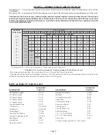
FRAMING DIMENSION CHART
FOR ATTIC INSULATION SHIELD
DIAMETER OF
CHIMNEY
FRAMED
OPENING
Table 2
5”
11 x 11
6”
12 x 12
7”
13 x 13
8”
14 x 14
7 -1/4”
11”
10“
13“
18 -1/2”
8 -1/4”
12”
10“
14“
18 -1/2”
9 -1/4”
13”
10“
15“
18 -1/2”
10 -1/4”
14”
10“
16“
18 -1/2”

