background image

Page 7

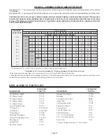
2

2.5

3

3.5

4

4.5

5

5.5

6

74

73

71

69

66

62

58

52

45

63

62

60

59

56

53

50

45

39

56

55

53

51

49

46

43

38

34

49

48

47

46

44

42

39

35

30

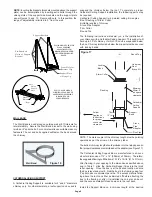
The following steps will assist you in the installation of  the
Adjustable Wall Support.  Figure 13 shows a typical Wall Support
installation.

To complete a proper Wall Support installation, the following
parts may be required:

-Adjustable Wall Support: Intended for a through-the-wall
installation where the chimney has a horizontal connection.
-Suitable Lengths of chimney: Installed above the support.
-Through-The-Wall Length: Attaches to tee branch.
-Insulated Tee w/Plug
-Insulated Wall Thimble: Required to pass through a combustible
wall.
-Wall Band: Required to provide lateral support to the chimney.
-Round Top: To prevent rain and/or debris from entering in the
chimney.
-Stove Pipe Adapter: To connect from the chimney to appliance’s
flue pipe.
-Roof Flashing: Required when the chimney penetrates a roof or
a roof overhang.

2.  For a non-combustible wall (concrete block or poured
foundation), cut a hole 5mm (3/16”) greater in diameter than the
outside diameter of the chimney as per Table 4.

1.  Determine the centre line of  the horizontal connection (length
through the wall) and frame an opening to the dimensions
specified in Table 4.

3.  After framing in your opening to the dimensions specified in
the Framing Dimensions in Table 1, install the outer half (with the
unfinished square plate) of the Insulated Wall Thimble in the
outside wall opening.  Secure in place using appropriate fasteners
through the pre-punched holes.

4.  Install the inner half (with black plate) of the Insulated wall
Thimble in the inside wall opening, ensuring that the shield slides
into the shield of the outer half.  Once in place and flush against
the wall, fasten with appropriate fasteners through the pre-
punched holes.

Distance from

Wall to

Chimney

5” ID

Chimney

6” ID

Chimney

7” ID

Chimney

8” ID

Chimney

H(feet)

Max. Height

H (feet)

Max. Height

H (feet)

Max. Height

H (feet)

Max. Height

D (inches)

Wall/Chimney

Table 5

 - 

Wall Support Chimney Height Chart

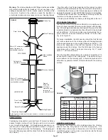
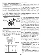
The maximum chimney height above an Adjustable Wall Support
is indicated in Table 5 and illustrated in Figure 8, all of which
must be above the support.

FIG. 8 - See Table 1 for Maximum Chimney

Heights based upon Chimney Diameter and

Distance from Wall

“H”

Max.

Chimney

Height

“D”

Distance

from Wall to

Chimney

Support Bracket

Support Plate

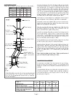
5.   Assemble the side Brackets (point of triangle facing down) to
the Support Plate (flange up) by inserting the threaded studs into
the oblong slots.  Install the supplied nuts on the threaded studs.
(see Figure 9 & 10).

Support Side

Brackets

Support Plate
Threaded Stud

Support Bracket
Threaded Stud

Nut

Support
Plate

Nuts

Nut

Support Bracket
Threaded Stud

Support
Plate
Threaded
Stud

FIG. 9 - UNDERSIDE VIEW OF

THREADED STUDS AND NUTS

Never offset an exterior chimney.

Summary of Contents for ULTRA-TEMP

Page 1: ...MATERIALS MODEL IT IS OF THE UTMOST IMPORTANCE THAT THIS CHIMNEY BE INSTALLED ONLY IN ACCORDANCE WITH THESE INSTRUCTIONS PLEASE READ ALL INSTRUCTIONS BEFORE BEGINNINGYOUR INSTALLATION FAILURETO INSTAL...

Page 2: ...ZING FRAMINGDETAILS CEILINGSUPPORT ATTICINSULATIONSHIELD FIRESTOPJOISTSHIELD ELBOWINSTALLATION ADJUSTABLEWALLSUPPORT WALLBAND CATHEDRALCEILINGSUPPORT ROOFSUPPORT ROOFFLASHING UNIVERSALROOFBRACEKIT ROU...

Page 3: ...chimney passes Safety gloves Safety goggles Hammer and nails Tin snips Tape measure Scewdrivers and pliers Plumb line and level Square Keyhole say or power jig saw Caulking gun and caulking Be sure th...

Page 4: ...uld conform to Table 1 2 With the Lower Bucket removed place the upper bucket assembly into the framed opening from below 3 Ensure that the support plate is level and flush and drive one nail 1 1 2 co...

Page 5: ...le contact of this material with the chimney surface FIRESTOP JOIST SHIELD A Firestop Joist Shield must be installed where the chimney passes from one living space to another living space It is instal...

Page 6: ...sections must pass vertically through framed joist areas ELBOW INSTALLATION Elbow Kits 2 elbows 1 offset support and 4 locking bands FIGURE7 Attic Insulation Shield Storm Collar Elbow Locking Bands I...

Page 7: ...ified in the Framing Dimensions in Table 1 install the outer half with the unfinished square plate of the Insulated Wall Thimble in the outside wall opening Secure in place using appropriate fasteners...

Page 8: ...t Brackets Threaded Stud and Nut located at rear of Support Plate Pre Punched Holes of Support Bracket Flange Up Holes for Retainer Clips FIG 10 FRONTVIEW OFWALLSUPPORTASSEMBLY Support Plate 6 Ensure...

Page 9: ...the Wall Band bracket to the wall using two 6d or 2 spiral nails For concrete walls use suitable masonry fasteners The nut and bolt supplied will fasten the band around the chimney Figure 16 After fra...

Page 10: ...Brackets to the roof pitch and tighten nuts Attach to the roof with six 6 large wood screws per bracket with the inner most screws going into the rafters or headers See Figure 18 19 9 Additional chim...

Page 11: ...he flashing under the roofing shingles At least half of the flashing top and sides should be UNDER the shingles and the lower end OVER the shingles to provide a watershed Trimming off the shingles may...

Page 12: ...top surface of the length Wrap the band snug to the bottom of the 3 tabs and secure in place with the supplied nut and bolt The connection of a single wall base tee or single wall flue pipe or double...

Page 13: ...artment 4 Do not use salt or water on the fire Salt is corrosive and water will cause a dangerous steam explosion You may be able to control the fire by using ashes sand or baking soda since baking so...

Page 14: ...eter 8 Diameter 5 Diameter 30o OFFSET CHART Chimney Lengths 7 Diameter 6 Diameter 8 Diameter 5 Diameter none 6 12 18 24 12 18 36 12 36 18 36 12 18 36 48 OFFSET CHART CHIMNEY INSTALLATION It may be nec...

Page 15: ...affect its performance If you think a nearby obstacle could affect draft you might want to install one or more additional lengths CHART 2 CHIMNEY HEIGHT ABOVE THE ROOF DISTANCE FROM PEAK 10 Ft 9 Ft 8...

Page 16: ..._______________________________________ Address ______________________________________________________ City _________________________________________________________ Province _________________________...

Reviews: