Page 8
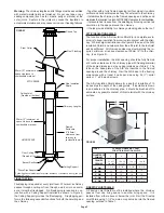
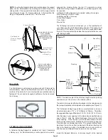
Insulated Wall Thimble
Telescoping adjustment
from 6” to 11”
Insulation
Blanket
Interior Inner
Half of
Insulated Wall
Thimble
Exterior Outer
Half of
Insulated Wall
Thimble
Figure 11
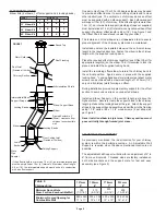
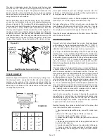
Insulated Wall
Thimble
Combustible Inside Wall
76mm (3”) min.
660mm (26”) max.
Insulated Chimney
Length
Min. Clearance to
Combustibles (50mm)
Fig. 13 - Wall Support
Installation
Lag Screws Into
Structure
Bracket
Support Plate
Wall Support Kit
Locking Band
Insulated Tee
Full Enclosure
Recommended.
Both Indoors
and Outdoors
Use Locking
Bands on All
Joints
Wall Band Every
8 Feet
9. Place the insulated Tee on the support plate ensuring that the
male coupler of the Tee is facing up and the flange on the top of
the plate slides into the female coupler. Insert and secure the Tee
Cap with the attached retainer clips (see Figure 12). In earthquake
zones, secure the Tee to the flange on the support plate by
installing 2 stainless steel sheet metal screws as per figure 12.
10. For extension of the Tee, slide an appropriate insulated
Chimney Length through the Wall Thimble and attach it to the
horizontal branch of the Insulated Tee with the supplied locking
band. Make sure the nut and bolt are facing down to prevent any
water from collecting in the locking band. The insulated length
must protrude at least 76mm (3”) through the wall into the room
as per Figure 13.
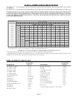
Stud and Nut
located to front
of Support
Bracket
Support
Brackets
Threaded Stud
and Nut
located at
rear of
Support
Plate
Pre-
Punched
Holes of
Support
Bracket
Flange Up
Holes for Retainer Clips
FIG. 10 - FRONT VIEW OF WALL SUPPORT ASSEMBLY
Support
Plate
6. Ensure that the Wall Support is level, and secure to the wall
through the pre-punched holes located on the sides of each of
the wall support brackets using (8) #14 x 1-1/2” hex head lag
screws or #10 x 1-1/2” wood screws. You can drill 5/32” pilot
holes for the lag screws.
7. Once in its final position and all clearances have been met,
tighten each of the nuts on the threaded studs.
8. Attach the two (2) retainer clips to the bottom of the support
plate and fasten with the supplied nuts and bolts using the two
(2) holes on top of the support plate (see Figures 10 & 12).
FIG. 12 - SECURING OF TEE CAP
Support
Plate
Retainer
Clip
Tee Cap
Earthquake zones
secure Tee to the
Support Plate
with stainless
steel screws
Insulated Tee
WARNING: Tee Cap and Retainers must be installed.
Failure to install retaining clips could cause fire,
injury or death.
Wing Nut
11. Use a non-hardening high-temperature sealant (500
o
F) to
seal around the horizontal length where it enters the wall thimble
or the concrete wall.
12. Chimney lengths above the Insulated Tee are simply stacked
on and locked with a 1/8 clockwise turn. Locking bands must be
used on all joints.
13. For lateral stability of the chimney above the support, a Wall
Band must be used every 8 feet, and at least one Wall Band
must be installed. Interior chimneys must use the Firestop Joist
Shield (JS) in place of Wall Bands if extending through floor /
ceiling penetrations.

