Kingfisher Plus+ Hardware Manual
11.
DIGITAL INPUT MODULES
Overview
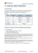
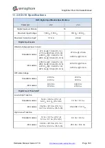
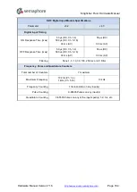
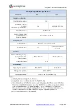
The Digital Input Modules allow various level digital signals to be interpreted by your RTU.
All modules provide a minimum of 1 kV field isolation, 16 input channels and can be
configured to use counters and input buffers to count incoming pulses.
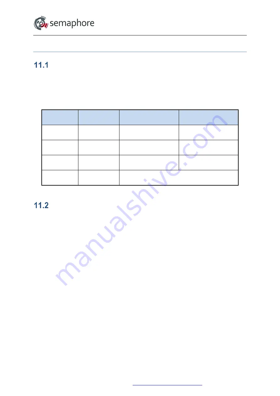
Summary:
Module
Maximum input
Voltage
Channel group 1
maximum capture speed
Channel group 2
maximum capture speed
DI-5-1
28 V
DC
Channels 1 and 2
10 kHz
Channels 3 and 4
255 Hz
DI-5-1-48
60 V
DC
Channels 1 and 2
10 kHz
Channels 3 and 4
255 Hz
DI-10-1
DI-10-1-48
+130 V
DC
125 V
AC
Channels 1 to 4
10 kHz
Channels 5 to 16
1 kHz
DI-10(-GPS)
DI-10-48(GPS)
+130 V
DC
250 V
AC
Channels 1 to 16
10 kHz
DI-5: DC Input 16 Channel Digital Input Module
11.2.1 Overview
•
Pulse counting on channels 1 to 4 (up to 10 kHz)
•
Positive or Negative Polarity Inputs
•
Isolated DC Outputs for powering inputs
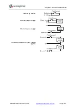
The DI-5 provides 16 input channels with one common. As a wide input voltage is accepted
a wide range of input devices can be used such as buttons, reed switches, line switches,
PIR sensors, and proximity sensors. Any combination of inputs powered externally or by the
modules own isolated DC supply (+12 V) can be used.
Applying a high input voltage results in logic 1 in the module’s status register. Low (or not
present) input voltages result in logic 0.
The DI-5 counter can also count pulses in the first 4 digital inputs. It is able to count up to
10 kHz on inputs 1 and 2 and can count up to 255 Hz on inputs 3 and 4. The pulse total and
the frequency for each of the first 4 digital inputs are stored.
This module can be installed in any I/O slot of a 4, 6 or 12 slot backplane system.
Hardware Manual Version 7.16
http://www.servelec-semaphore.com/
Page 150

