06/2017
- 6 -
Copyright © 2017, Fast ČR, a.s.
EN
Electric Spiralizer
User's manual
■
Prior to using this appliance, please read the user’s manual thoroughly,
even if you already have experience in using similar appliances. Only
use the appliance in the manner described in this user’s manual. Keep
this user’s manual in a safe place where it can be easily retrieved for
future use.
■
We recommend saving the original cardboard box, packaging
material, purchase receipt and responsibility statement of the vendor
or warranty card for at least the duration of the legal liability for
unsatisfactory performance or quality. In the event of transportation,
we recommend that you pack the appliance in the original box from
the manufacturer.
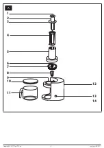
DESCRIPTION OF THE APPLIANCE
A1
Button for releasing the
extension of the inner part of
the pusher
A2
Inner part of the pusher
A3
Pusher outer case cover
A4
Pusher outer case
A5
Lid with feed tube
A6
Blade holder with a peripheral
cog wheel
A7
Blade for cutting spaghetti
strips measuring 3 × 3 mm
A8
Blade for cutting spirals,
cutting thickness 3 mm
A9
Insertion hole for the blade
holder
A10
Jug lid
A11
1.7-litre transparent jug
A12
Drive unit
A13
0/I switch (off/on)
A14
Anti-slip feet
BEFORE FIRST USE
1. Take the appliance and its accessories out of the packaging materials.
2. Thoroughly wash all parts that are intended to come into contact with
food using warm water and a neutral kitchen detergent. Then rinse
under clean water and allow them to dry naturally or dry them using a
wiping cloth. Do not submerge the drive unit
A12
in water or rinse it
under running water.
Attention:
Be especially careful when cleaning the blades
A7
and
A8
to
avoid injury on the sharp edges.
ASSEMBLING AND DISASSEMBLING THE APPLIANCE
■
Before you start assembling or disassembling the appliance, check
that it is turned off and disconnected from the power socket.
■
Place the drive unit
A12
on an even, dry and stable surface. Place
the jug
A11
under the insertion hole
A9
so that the handle points
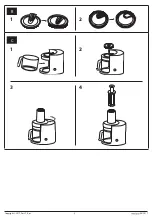
outwards and so that it is properly seated in its place (see fig.
C1
).
Otherwise, the appliance will not start when turned on. The lid
A10
serves to cover the jug
A11
when it is not located in the drive unit
A12
, for short term food storage.
■
Insert the blade
A7
or
A8
from above into the holder
A6
and push
down the blade edges to that the blade fits in along the entire
perimeter of the holder
A6
(see fig.
B1
).
Attention:
When inserting blade
A7
or
A8
into the holder
A6
take care not
to injure yourself on its sharp edges.
■
Insert the assembled holder with the blade from above into the
insertion hole
A9
ensuring that the peripheral cog wheel on the
holder
A6
slides into the cog wheel that is a part of the drive unit
A12
(see fig.
C2
). On to the drive unit
A12
place the lid with the feed tube
A5
so that the arrow symbol marked on the lid
A5
is aligned with the
open padlock symbol marked on the drive unit
A12
(see fig.
C3
). Turn
the lid
A5
clockwise all the way to secure it in position. The arrow
symbol marked on the lid
A5
is now aligned with the closed padlock
symbol on the drive unit
A12
. Unless the lid
A5
is properly attached,
the appliance will not start when turned on.
■
Into the outer case
A4
insert the inner part of the pusher
A2
, and to
connect these two parts press the cover
A3
towards the outer case
A4
while at the same time turning it anticlockwise all the way. Insert
the pusher assembled in this way into the feed tube
A5
(see fig.
C4
).
Button
A1
serves to release the extension of the inner part of the
pusher
A2
. When button
A1
is pushed, the inner part of the pusher
A2
will extend out upwards. This will release the remaining foodstuffs
from the bottom part of the pusher when the appliance is used. Lock
the extension in place by pushing the inner part of the pusher
A2
down into the outer case
A4
until it is secured in place by both latches
on the inner part of the pusher
A2
in the cover
A3
.
■
Disassemble the appliance in the reverse sequence. To remove the
blade
A7
or
A8
from the holder
A6
, it is first necessary to push down
the latches of the blade
A7
or
A8
from underneath (see fig.
B2
). This
will release the blades and it is then possible to remove them.
OPERATING THE APPLIANCE
1. This appliance is suitable for processing harder types of fruits and
vegetables such as, for example, carrot, apple, celery, zucchini,
cabbage, beetroot, pumpkin, cucumber, potatoes, sweet potato, etc.
in the raw form. It is not particularly suitable for processing soft types
of fruits and vegetables.
2. Thoroughly wash all the fruit and vegetables. Certain types may need to
be cut up to pass through the hole of the feed tube
A5
. This means that
the diameter of the fruit or vegetable should not be greater than 75 mm
and the length should be no greater than 175 mm. Kernels and stones
also need to be removed from certain types of fruit and vegetables.
Attention:
Never attempt to use this appliance to process hard stones
contained in, for example, mangoes, etc.
3. Make sure that the appliance is properly assembled and located on
an even, dry and stable surface. Connect the power plug to a power
socket and set the switch
A13
to position I (on).
4. Start gradually inserting the fruit or vegetables into the hole of the
feed tube
A5
and push them through the feed tube
A5
with the
properly assembled pusher. To release any remaining foodstuffs from
the bottom part of the pusher, use button
A1
as described in chapter
Assembling and disassembling the appliance.
Attention:
Do not use fingers or other items to push food in.
The maximum continuous operating time is 1 minute. Before
turning it on again, allow the appliance to cool down for at least
5 minutes.
5. In the event that the jug
A11
fills up during operation, turn off the
appliance, disconnect it from the power socket and make sure that the
rotating parts have stopped. Empty the jug
A11
and put it back in its
place. Then you can use the appliance again.
6. When you have finished using it, set the switch
A13
to position 0
(off), disconnect the appliance from the power socket and clean it out
according to the instructions contained in the chapter Cleaning and
maintenance.
QUICK GUIDE TO PROCESSING FRUIT AND VEGETABLES
Type of fruit or
vegetable
Type of blade
Maximum
amount per
batch
Approximate
operating
time
Carrot
A7
or
A8
500 g
30 s
Potatoes
A7
or
A8
500 g
30 s
Cucumber
A7
or
A8
500 g
30 s
Cabbage
A7
500 g
30 s
Zucchini
A7
or
A8
500 g
30 s

