SMD 989
– User Manual
Page 26 (105)
IP Inputs (SMD 910)
The IP inputs to the SMD 910 modulator are shown on the left column of the home screen for
each bay. The available IP inputs are listed in rows under the ASI inputs. Each IP input has
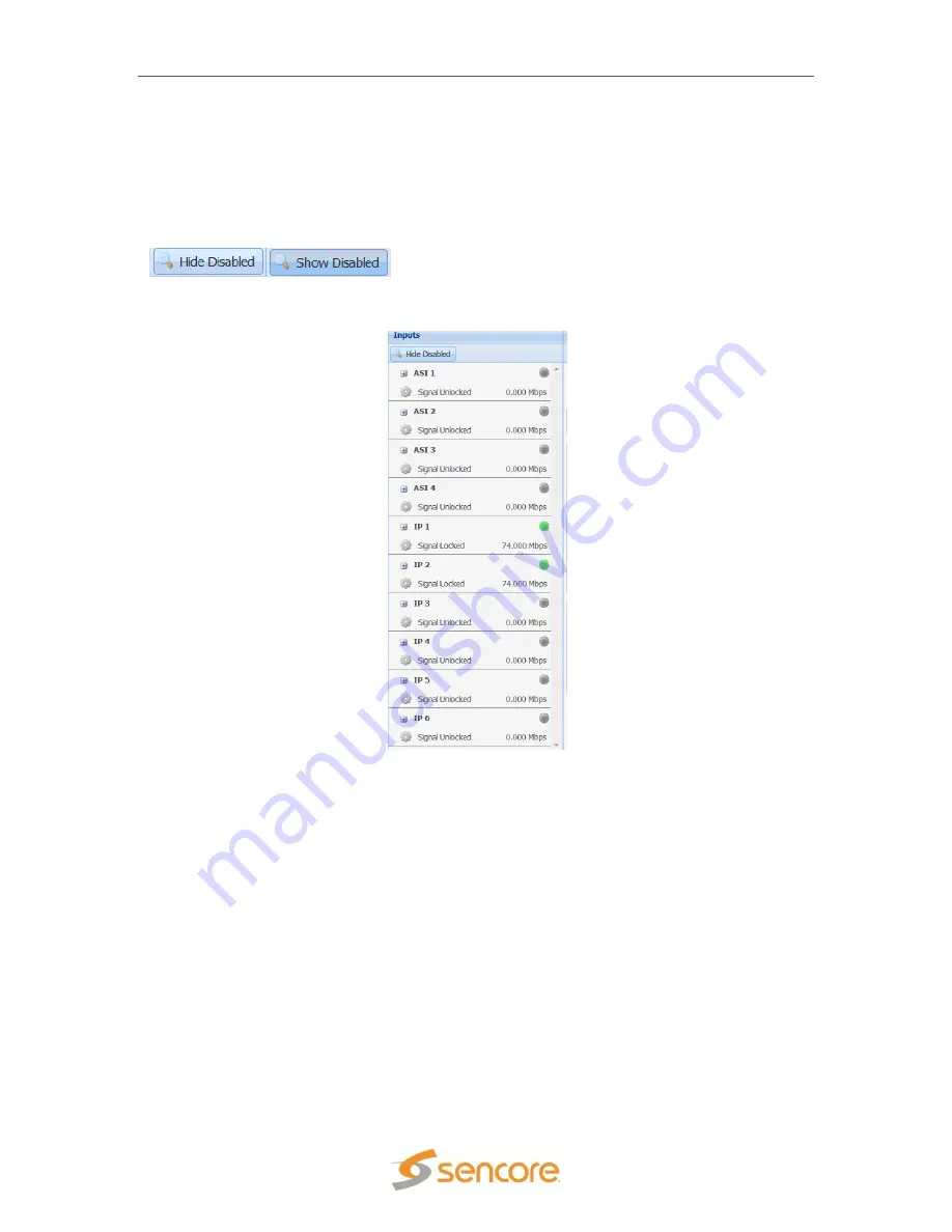
either an enabled or disabled status. To see all the possible IP inputs, click on the Show Disabled
tab. To see only the enabled inputs, click on the Hide Disabled tab. Depending on the unit
licensing the IP inputs that are enabled by default and listed may be different.
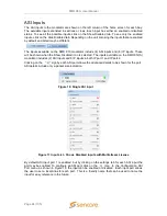
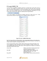
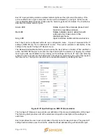
The IP inputs available on the SMD 910 modulator include (6) IP inputs via IP port 1. These
inputs are shown when the Show Disabled icon is selected as shown in Figure 19.
Figure 19 Inputs on SMD 910 Modulator
Each IP input port listing or section contains an active input bitrate indication on the right side of
the section. When the input is enabled and an active transport stream is present on that input, the
bitrate counter indicates the incoming bitrate in Mbps.
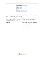
Each IP input port listing contains a status indicator light near the right side of the listing. If the
port is enabled and no sync is detected, an error will be indicated by a red light. Errors can be
user enabled/disabled if desired. Please see the Alarm/Logs Section for details. The chart below
describes the status indicator lights.
Green LED
Status is good. No errors are present and
function is operating normally.
Red LED
Status indicates input is active but with
active error(s). View errors in the
Alarms/Logs menu
Grey LED
Input is inactive and/or alarms are inactive

