SMD 989
– User Manual
Page 30 (105)
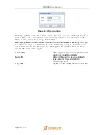
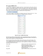
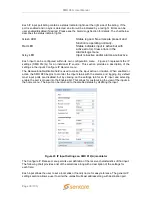
Each IP input port listing contains a status indicator light near the right side of the listing. If the
port is enabled and no sync is detected, an error will be indicated by a red light. Errors can be
user enabled/disabled if desired. Please see the Alarm/Logs Section for details. The chart below
describes the status indicator lights.
Green LED
Status is good. No errors are present and
function is operating normally.
Red LED
Status indicates input is active but with
active error(s). View errors in the
Alarms/Logs menu
Grey LED
Input is inactive and/or alarms are inactive
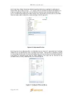
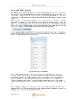
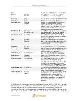
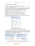
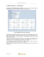
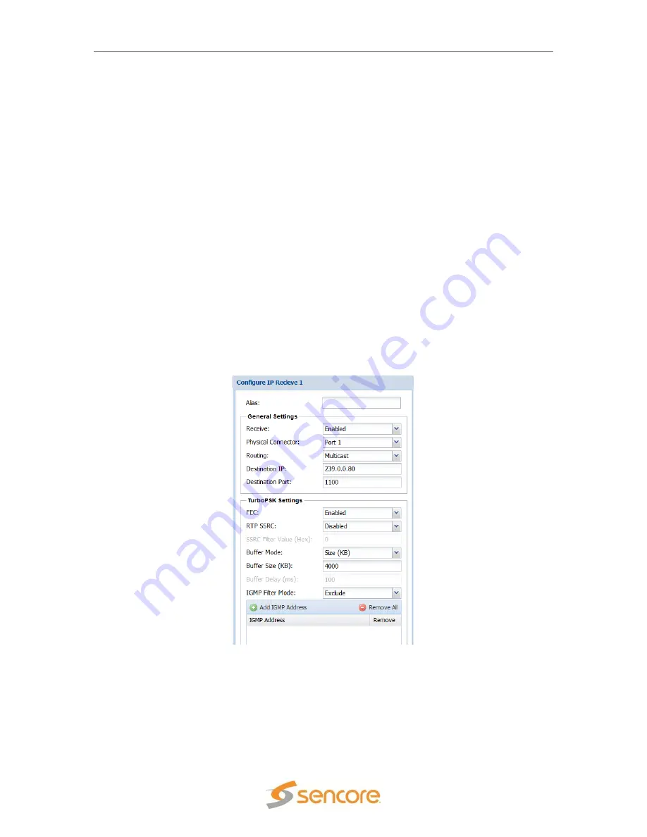
Each input can be configured within its own configuration menu. . Figure 23 represents the IP
settings (SMD 912(A)) for an individual IP source. This section provides a description of the
settings in the input’s Configure IP Receive menu.
The Receive Enable/Disable field is used to make the input active or inactive. When enabled or
active the SMD 989 begins to monitor the input status with the alarms and logging. By default
most input ports are disabled, but by clicking on the settings tab for an IP input and selecting
enable the port is moved into the Enabled list. This allows for customizing the view of the inputs in
the home menu. The input can be returned to the disabled status by disabling the input.
Figure 23 IP Input Settings on SMD 912(A) modulator
The Configure IP Receive menu permits user definition of the receive characteristics of that input.
The following chart provides a list of the selections along with a description of the settings for
each field.
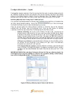
Each input allows the user to set a local alias or friendly name for easy reference. The general IP
settings section allows a user to enter the unicast/multicast address along with destination port.

