SMD 989
– User Manual
Page 54 (105)
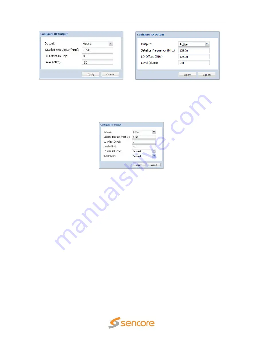
If the RF L-Band SMD 920 option is installed along with 10 MHz BUC Power SMD 94X option the
ability to configure the RF output as well as the ability to enable or disable the 10MHz Ref. Clock
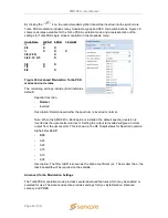
and the BUC Power is also shown. By clicking on the “
Configure RF Options,
” a dialog box will
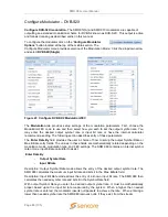
appear as shown in Figure 46. Enabling the 10 MHz Ref. Clock or BUC Power will diplex them
with the L-Band PRI RF output looped to the optional SMD 94X LOOP IN.
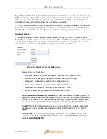
The parameters shown in blue in the RF Output section indicate the status of that parameter and
cannot be edited in the RF Output configuration window. These statuses are:
-
RF Frequency
: This is determined by the calculation of the Satellite Frequency and
the L.O. Offset frequency.
-
IF Input Level:
This indicates OK if the IF input is at the proper level. The Level
indication can be “Low”, “OK” or “High.” If this does not show OK as the status, check
that the IF output is set to -10dBm. If the level indicates LOW or HIGH you may
increase or decrease the IF Level slightly to return the IF Input Level to OK status.
This provides the optimum spectral output performance of the RF upconverter.
-
Oscillator Status:
Indicates if the 10MHz reference is locked to the incoming IF.
-
Output Status:
Indicates Present when the output is active, or Missing if the output
is muted.
-
Spectral Inversion:
This reflects what the RF output will be after the RF
upconverter. This indication changes depending on the Spectral Inversion setting in
the Configure Modulation Options. If the Spectral Inversion is set to Normal in the
modulation configuration, the RF Output will be inverted. If the Spectral Inversion is
set to Inverted in the modulation configuration, the RF Output will be normal.
Figure 45: RF settings
Figure 46: RF settings with 10MHz option

