SMD 989
– User Manual
Page 66 (105)
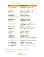
Name
Description of Trap
10MHz Ext. Ref Clock Error
Indicates
the unit’s external reference source has
changed between either internal or external.
12V Supply Error
Unable to detect 12V from Power Supply
3V Supply Error
Unable to detect 3V from Power Supply
5V Supply Error
Unable to detect 5V from Power Supply
ASI TS Sync Error
No ASI Sync with TS Input
ASI Bitrate Error
ASI Input Bit Rate Error
Backup Input Active
Unit switched to backup Input
Fan Speed Below Lower Limit
A fan failure has been detected
FEC Reception Error
Error in FEC detected
IF Output Mute Error
Indicates the IF output is muted
IP Loss Error
Indicates MPEG/IP Data loss
MPEG/IP Bitrate Error
Indicates IP Bit Rate Error
MPEG/IP NIC Link Error
Indicates the MPEG/IP Data Link is broken
MPEG/IP TS Sync Error
Indicates MPEG/IP Data interface cannot sync
with the TS
RTP Reception Error
RTP reception errors indicated
Output Buffer Error
Data underflow/overflow in buffer, rate adaption
issue where TS packets are discarded
TS Continuity Count Error
TS Analysis
– CC Error indicated in TS Header
TS ES PID Error
TS Analysis
– PID error in ES
TS PAT Error
TS Analysis
– PAT CC error
TS PMT Error
TS Analysis
– PMT CC error
TS Sync Byte Error
TS Analysis
– TS sync byte
TS Sync Loss Error
TS Analysis
– Sync Loss
Temperature Error
Internal temp. is outside range of 0 to 45 Celsius
Upconverter IF Input Freq. Error
Not within auto-lock range of 70 or 140 MHz
Upconverter IF Input Level Error
Indicates IF input is not within the acceptable level
range for the upconverter
Upconverter Mute Error
Indicates the RF upconverter is muted
Upconverter Oscillator Error
Indicates a loss of oscillator or communication
Upconverter Output Error
Indicates loss of RF upconverter output or system
communications
Figure 75: Alarm descriptions
Error handling voltage and temp limits that will trigger an alarm if exceeded:
3 Volt Controller Supply

