SMD 989
– User Manual
Page 72 (105)
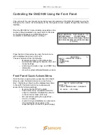
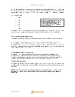
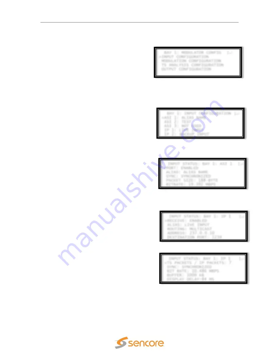
BAY 1: MODULATOR CONFIG
↕
>INPUT CONFIGURATION
MODULATION CONFIGURATION
TS ANALYSIS CONFIGURATION
OUTPUT CONFIGURATION
BAY 1: INPUT CONFIGURATION
↕
>ASI 1: ALIAS NAME
ASI 2: TEST
ASI 3: NOT USED
IP 1: LIVE INPUT
IP 2:
BACKUP INPUT
INPUT STATUS: BAY 1: ASI 1
↕
>PORT: ENABLED
ALIAS: ALIAS NAME
SYNC: SYNCHRONIZED
PACKET SIZE: 188-BYTE
BITRATE: 19.392 MBPS
INPUT STATUS: BAY 1: IP 1
↕
>RECEIVE: ENABLED
ALIAS: LIVE INPUT
ROUTING: MULTICAST
ADDRESS: 237.0.0.10
DESTINATION PORT: 1234
INPUT STATUS: BAY 1: IP 1
↕
>TS PACKETS / IP PACKETS: 7
SYNC: SYNCHRONIZED
BIT RATE: 10.486 MBPS
BUFFER: 1000 KB
DISPLAY DELAY:84 MS
Front Panel Modulator Settings
Select the modulator settings from the main menu,
the user will be able to set input, modulation, and
output parameters for the given bay the modulator is
installed.
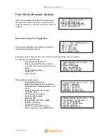
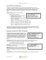
Modulator Input Configuration
Once input configuration is selected, all available
inputs ASI and IP will be shown.
Selecting any of the specific ASI or IP ports, the individual settings can be modified.
ASI Settings and status include:
-
Enabling/Disabling the port
-
Entering an alias that can be used to
name the input for easy reference in the
future
-
Synchronization status
-
Packet size
-
Bitrate (Mbps)
IP Settings and status include:
-
Enabling/Disable the port
-
Entering an alias that can be used to
name the input for easy reference in the
future
-
Routing: Destination IP address
-
Destination port
-
TS Packets per IP packet
-
Synchronization status
-
Bitrate (Mbps)
-
IP input buffer (100 KB
– 4 MB)
-
IP IGMP versioning
-
Transport Protocol
-
Packet Counters (SMD 912(A))
-
FEC Row/Column Info (SMD 912(A))

