SMD 989
– User Manual
Page 24 (105)
ASI Inputs
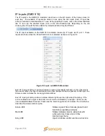
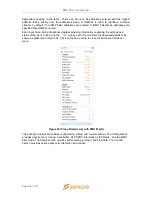
The ASI inputs to the modulator are shown on the left column of the home screen for each bay.
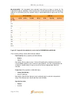
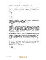
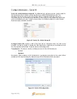
The available inputs are listed in sections or rows. Each input has either an enabled or disabled
status. To see all the possible inputs, click on the Show Disabled tab. To see only the enabled
inputs, click on the Hide Disabled tab. Depending on the unit licensing the inputs that are enabled
by default and listed may be different.
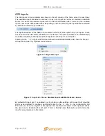
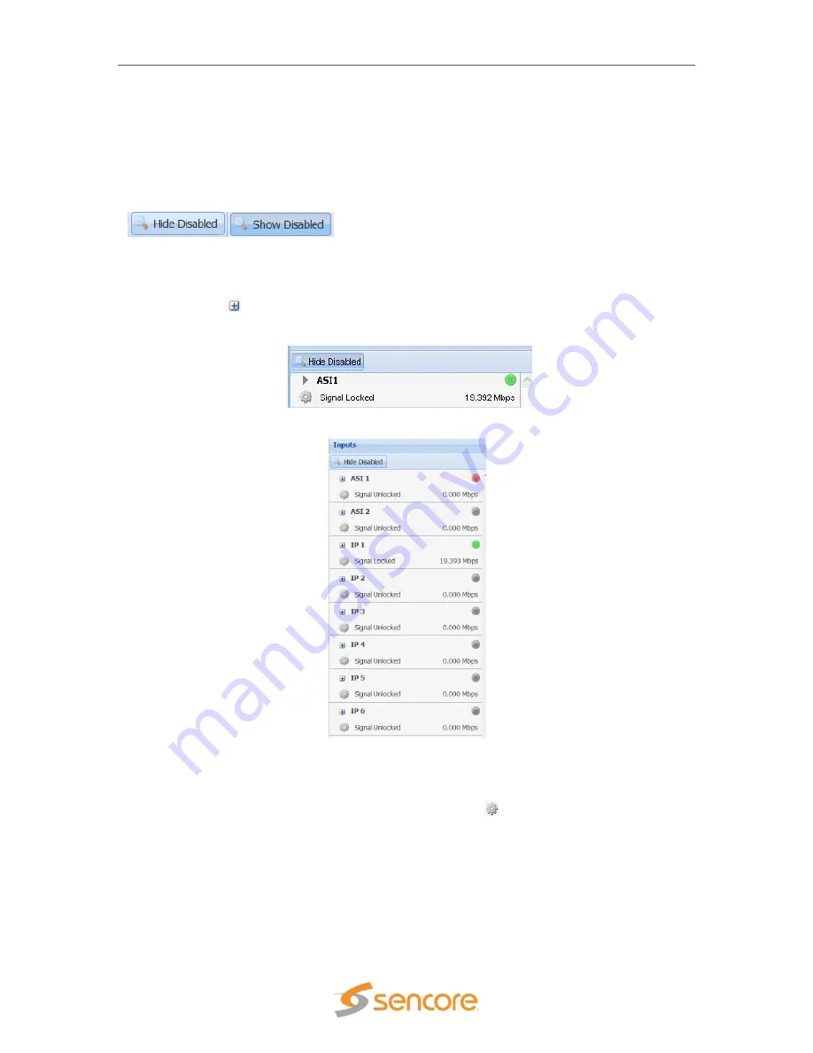
The inputs available on the SMD 910 modulator include (4) ASI inputs and (6) IP inputs. These
will be shown when the Show Disabled icon is selected. The inputs available on the SMD 912(A)
modulator includes (2) ASI inputs and 6 IP inputs in both IP port 1 and IP port 2.
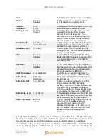
Clicking on the
“
” sign by each ASI port allows the advanced details to be shown for the port.
ASI details include only a packet size indication.
Figure 17 Input List - Shows Disabled inputs with Multistream License
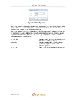
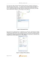
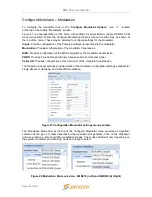
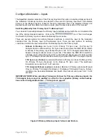
By default ASI input port 1 is enabled, but by clicking on the settings tab for each ASI input the
port may be enabled. To configure an ASI port, click on the
Icon. In the Configuration ASI
Port menu, as shown in Figure 18, the input can be enabled or disabled. Each input port allows
the user to set a local Alias for each port. This is a friendly name that can be used to name the
input for easy reference in the future.
Figure 16: Single ASI input

