SMD 989
– User Manual
Page 29 (105)
IP Inputs SMD 912(A)
The SMD 912(A) or SMD 912(A) provides two physical IP input ports compared to one port on
the SMD 910. It further provides RTP/FEC receive capabilities along with configuration of the
input buffer by delay time. The IP inputs are also monitored for FEC status information and errors.
This section provides details of IP input settings and monitoring details when using the SMD
912(A) modulator.
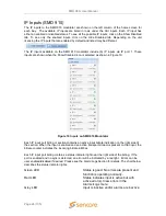
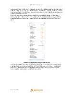
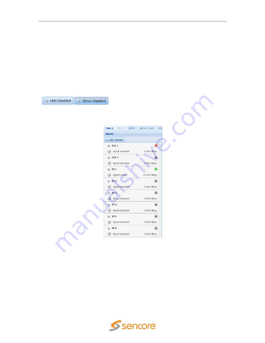
The IP inputs to the SMD 912(A) modulator are shown on the left column of the home screen for
each bay. The available IP inputs are listed in rows under the ASI inputs. Each IP input has
either an enabled or disabled status. To see all the possible IP inputs, click on the Show Disabled
tab. To see only the enabled inputs, click on the Hide Disabled tab. Depending on the unit
licensing the IP inputs that are enabled by default and listed may be different.
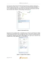
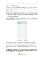
The IP inputs available on the SMD 912(A) modulator include (6) IP inputs. These six inputs may
be sourced from either IP port 1 or IP port 2. These six possible inputs are shown when the Show
Disabled icon is selected as shown in figure 22.
Figure 22 IP inputs on SMD912
The modulator setup provides a user selection of a primary and backup input routed to the
modulator. This is explained in the next section of this manual. The primary and backup inputs
are selected from the list of inputs on the left side of the home menu. For normal operation the
primary and backup inputs must be selected from listed inputs that are enabled and actively
receiving an input transport stream. The DVB-S/DSNG single-stream, DVB-S2 CCM single-
stream, DVB S2X single-stream or TurboPSK modulation modes default the primary input to ASI
1.
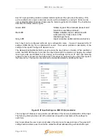
Each IP input port listing or section contains an active input bitrate indication on the right side of
the section. When the input is enabled and an active transport stream is present on that input, the
bitrate counter indicates the incoming bitrate in Mbps.

