SMD 989
– User Manual
Page 74 (105)
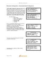
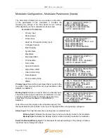
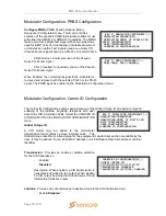
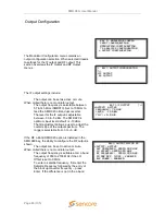
BAY 1: MODULATION MODE ↕
>MODULATION PARAMETERS
MODULATION MODE: S2 MULTI-CCM
BISS CONFIGURATION
PRBS CONFIGURATION
CARRIER ID CONFIGURATION
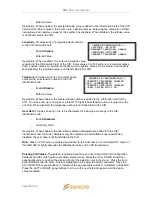
BAY 1: MODULATOR CONFIG ↕
INPUT CONFIGURATION
>MODULATION CONFIGURATON
TS ANALYSIS CONFIGURATION
OUTPUT CONFIGURATION
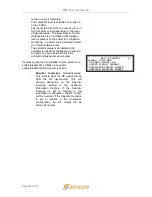
BAY 1: MODULATION CONFIG ↕
>PRIMARY INPUT: ASI1
BACKUP INPUT: IP1
ACTIVE INPUT: ASI1 (PRIMARY)
SWITCH TO BACKUP INPUT
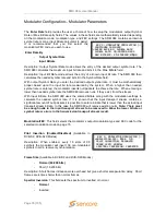
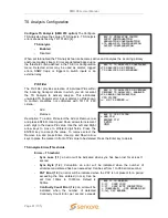
BAY 1: MODULATOR MODULATION ↕
>CONFIGURE FAILOVER
ENTER RATE BY: SYMBOL RATE
SYMBOL RATE: 38.000000 MSPS
MAX BITRATE: 49.4564248
Mbps
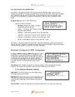
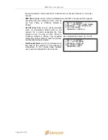
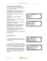
BAY 1: MODULATOR MODULATION ↕
>MODULATION FEC: 8PSK 5/6
PILOT INSERTION: DISABLED
FRAME SIZE: NORMAL
SPECTRAL INVERSION: INVERTED
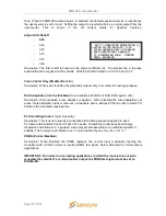
BAY 1: MODULATOR MODULATION ↕
>ALPHA FILTER ROLLOFF: 0.35
CLEAN CARRIER ONLY: DISABLED
RATE ADAPTATION: ENABLED
PL SCRAMBLING CODE: 000000
PRBS: DISABLED
Modulator Configuration
– Modulator Parameters (Inputs)
The Modulation Parameters menu provides configuration
of the parameters of the modulator. It includes the
following line listings in the front panel menus. Listings
differ depending on the modulation mode selected.
Modulation Parameters
-
Primary Input
-
Backup Input
-
Active Input
-
Switch to Primary/Secondary Input
-
Configure Failover
-
Enter Rate By
-
Symbol Rate
-
Max Bitate
-
Modulation/FEC
-
Pilot Insertion
-
Frame Size
-
Spectral Inversion
-
Alpha Filter rollfoff
-
Clean Carrier Only
-
Rate Adaption
-
PL Scrambling Code
-
PRBS
Primary Input
: Selects the input signal that is routed to the
modulator. User may select from any input available on the
SMD910 or SMD912.
Backup Input
: Selects an input to serve as a backup input
should the primary input meet failover conditions or a user
desires to switch manually to a backup input. User may
select from any input available on the SMD910 or
SMD912.
Note: When selecting inputs to the modulator be sure that
the inputs selected are enabled in the Input Configuration Menu and properly configured.
Active Input
: This field indicates the currently active or selected input.
Primary Input
; Indicates the Primary Input is active and being routed to the modulator.
Backup Input
: Indicates the Backup Input is active and being routed to the modulator
Switch to Backup/Primary Input:
This field permits manual switching to the primary or backup
input from the currently active input.

