background image

34 

4.6  Configure Wireless related parameters  

Click 

General Cofig, Wireless

.


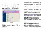
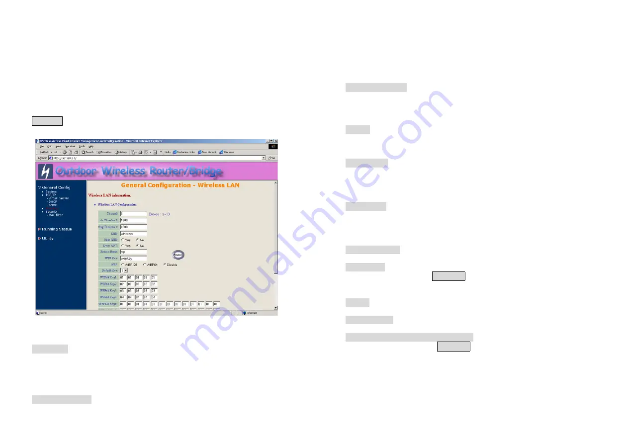
The Wireless LAN information page 

Figure 

4-10 

appears. In here, enter the 

Channel


(default is

 1

)

,

 rts Threshold


(default is

 1600

)

frag Threshold


(default is

 1600

)

SSID


(default is


wireless

) and 

Station Name


(default is 

ap

) that are suitable for your radio 

network and then you can clicked radio button to disable WEP or enable 
64/128 bit 

WEP services

 (default is 

disable

), if WEP is enabled, you must 

input corresponded 

Default Key


index

 and 

WEP Key 

and then click 


KeyGen


 to generate the WEP64 & WEP128 key patterns. After that, click 

FINISH

 at the bottom of this page to complete the modification.  


Figure 4-10 


- Channel.


The factory setting is Radio Channel 1 transmitting at 2412 MHz. 

The channel set appears on the screen installed on your access. Each 
channel covers 22 MHz. The bandwidth for channels 1, 6, and 11 does not 
overlap, so you can set up multiple access point in the same vicinity without 
causing interference.


- RTS Threshold.

 This setting determines the packet size at which the 

35 

bridge issues a request to send (RTS) before sending the packet. A low 
RTS Threshold setting can be useful in areas where many client devices 
are associating with the access point, or in areas where the clients are far 
apart and can detect only the bridge and not each other. Enter a setting 
ranging from 0 to 2339 bytes.


- Frag Threshold

. This setting determines the size at which packets are 

fragmented (sent as several pieces instead of as one block). Enter a setting 
ranging from 256 to 2338 bytes. Use a low setting in areas where 
communication is poor or where there is a great deal of radio interference. 


- SSID.


The 

Service Set ID (SSID) 

can be any alphanumeric, case-

sensitive entry from two to 32 characters long. This string functions as a 
password to joint the radio network.


- Hide SSID.

 You use this setting to choose whether devices that do not 

specify an SSID are allowed to associate with the access point. With Yes


selected, the SSID used by other devices must match exactly the AP’s 
SSID. 
 

- Deny Any

. You use this setting to choose whether devices that specify


the well define SSID keyword ‘ANY’ or ‘any’

 are allowed to associate 

with the access point. With 

Yes 

selected, the SSID 

‘ANY’ or ‘any’


used by 

other devices


are not allowed to associate with the access point  


- Station Name.

 Enter any alphanumeric, case-sensitive entry.  


- WEP Key

. Enter 1~15 characters for 64 and 128 bits WEP KEY 

encryption, and then click 


KeyGen


 to generate the WEP64 & WEP128 

key patterns. 
 

- WEP.


Disable

 or 

enable

 64/128 bit WEP services. 


- Default Key

. Select an encryption key from the pull down menu.  


- WEP64 Key1~4 & WEP128 Key1~4

. The keys in these fields can be 

generated automatically by 


KeyGen


 function. For 40-bit encryption, enter 

10 hexadecimal digits; for 128-bit encryption, enter 26 hexadecimal digits. 
Hexadecimal digits include the numbers 0 through 9 and the letters A 
through F. Your 40-bit WEP keys can contain any combination of 10 
of these characters; your 128-bit WEP keys can contain any combination of 
26 of these characters. The letters are not case-sensitive.  

Summary of Contents for ORB-02001

Page 1: ...ESS ROUTER 11 2 4 REMOTE WIRELESS ROUTER TO CENTRAL WIRELESS ROUTER 12 CHAPTER 3 WEB ACCESS 13 CHAPTER 4 CONFIGURATION 17 4 1 INTRODUCTION 17 4 1 1 Basic Configuration Steps 17 4 2 SYSTEM SETUP 19 AFTER THAT CLICK FINISH AT THE BOTTOM OF THIS PAGE TO COMPLETE THE MODIFICATION OF THIS PAGE 23 AFTER THAT CLICK FINISH AT THE BOTTOM OF THIS PAGE TO COMPLETE THE MODIFICATION OF THIS PAGE 24 AFTER THAT ...

Page 2: ...HAPTER 8 REGULATORY COMPLIANCE INFORMATION 54 1 Chapter 1 Hardware Installation This chapter describes the procedures for installing the Outdoor Router Bridge Note Before you mount the Router Bridge to a mast or on the side of a building be sure to configure and test the device first 1 1 Before You Start After unpacking the system make sure the following items are present and in good condition 1 R...

Page 3: ...nfigure and test all the devices first For configuring the Outdoor Router Bridge you need follow the quick steps below to power up your Router Bridge Step 1 With the unit powered off attach one end of the RF cable to the antenna connector and then connect the antenna to the other end of the RF cable as shown in following Step 2 Plug the female end of the power cord into the Inline Power Injector a...

Page 4: ...will light up You can configure the Router Bridge using the HTML browser such as Internet Explorer or Netscape Navigator from a remote host or PC NOTE The outdoor Router Bridge antenna cabling systems be identified by Reverse Polarity N connectors pictured in following 5 1 4 Outdoor Installation Outdoor Router Bridge device can be mounted on the side of a building or mounted to an antenna mast as ...

Page 5: ...ge Arrester So Mounting the Outdoor Router Bridge on the antenna mast you have to connect the Outdoor Router Bridge to the same grounding system with the AC wall outlet The grounding system must comply with the National Electrical Code and safety standards that apply in your country Always check with a qualified electrician if you are in doubt as to whether your outdoor installation is properly gr...

Page 6: ...tdoor Wireless Router Bridge product the centralized agent is Central Router or Central Bridge and the individual network notes may be Remote Router or Remote Bridge To show some possibilities of Point to Multipoint topologies the following examples are provided 1 Remote Wireless Bridge to Central Wireless Bridge 2 Remote Wireless Router to Central Wireless Bridge 3 Remote Wireless Bridge to Centr...

Page 7: ...The Remote RB assign IP address to PC1 and PC2 11 2 3 Remote Wireless Bridge to Central Wireless Router 1 Set the Central RB run as a Wireless Router Wireless Interface IP is 192 168 1 1 Ethernet Interface IP is 192 168 2 1 must turn on NAT on Ethernet interface default route is 192 168 2 254 2 Set Wireless parameters on Central RB Channel 1 and SSID wireless 3 Set the DHCP server service on the C...

Page 8: ... RB supports access to the configuration system through the use of an HTTP Interface web browser Before configuring the RB you need to know the IP Address assigned to the unit When shipped from the factory the IP Address 192 168 2 1 was assigned to the RB by default To start a web connection use http 192 168 2 1 Identify the IP Address assigned to the unit However the IP Address may be changed and...

Page 9: ... to configure each item 1 Open your browser and enter the IP Address 2 Press ENTER and the RB Login screen appear 15 Figure 3 2 Login Screen 3 Enter root in the User Name and the Password fields And then the web configuration user interface screen appears Figure 3 3 Web User Interface Web Configuration Structure The web configuration user interface be grouped in a tree structure and contains the f...

Page 10: ...des Central Wireless Bridge Central Wireless Router with PPPoE Ethernet connection Central Wireless Router with dynamic IP address Ethernet Central Wireless Router with static IP address Ethernet Remote RB can performed in two operation modes Remote Wireless Bridge Remote Wireless Router The RB is shipped with default configuration is as a bridge between an Ethernet and wireless network Users simp...

Page 11: ... page General Config page and click FINISH to save your changes 5 Move on page Utility Administration select the Save then Restart and then click FINISH to take effect the previous configuration changes 19 4 2 System Setup When setting up a SendFar Wireless Router Bridge RB you must decide which operation mode that your RB works This feature is available in the General Config System page Figure 4 ...

Page 12: ...his page to complete the modification of this page Remote Extension Bridge Select the Remote Wireless Bridge mode And then set the corresponding parameters Bridge IP Address Use this setting to assign or change the bridge s IP address Bridge Subnet Mask Enter an IP subnet mask to identify the sub network so the IP address can be recognized on the LAN Default Route IP IP Address Enter the default G...

Page 13: ...sign or change the wireless interface s IP address 23 Subnet Mask Enter an IP subnet mask to identify the sub network so the IP address can be recognized on the WLAN NAPT performs on which interface There are three interfaces You can select one to use or select None to disable it Default Route IP IP Address Enter the default Gateway IP Address DNS Server IP Primary DNS Server IP Enter the Primary ...

Page 14: ...he sub network so the IP address can be recognized on the WLAN Ethernet Interface Address IP Address Use this setting to assign or change the Ethernet interface s IP address Subnet Mask Enter an IP subnet mask to identify the sub network so the IP address can be recognized on the WAN NAPT performs on which interface There are three interfaces You can select one to use or select None to disable it ...

Page 15: ...as FTP 27 Access Interface Indicate the translation occurs on which interface Wireless interface Ethernet interface such as Ethernet Protocol Indicate which protocol TCP UDP you want to translate from outside to internal server such as TCP Public Access Port number Indicate which socket port 1 65535 you want to translate from outside to internal server such as 21 Virtual Server IP address Specify ...

Page 16: ...ddress Subnet Mask Configure the subnet for the client Name Server 1 2 3 Configure the DNS servers IP for the client DHCP Start IP address Enter the starting IP Address for this IP Pool Table DHCP End IP address Enter the ending IP Address for this IP Pool Table Apply Interface Enable DHCP server service on Wireless or Ethernet interface 4 4 2 Fixed Host Entries Figure 4 5 shows the general DHCP p...

Page 17: ...y Parameter screen appears Figure 4 7 shows the current SNMP community pool and trap host pool Figure 4 7 General Configuration SNMP Community Parameter 4 5 1 Configure Community Pool The SNMP Community Pool has five entries 1 To modify a entry click the select button beside the entry index number and then click Modify the configuration page Figure 4 8 appears 2 Specify the Validity Access Right a...

Page 18: ...Trap Host Pool has five entries 1 To modify a entry click the select button beside the entry index number and click Modify The configuration page Figure 4 9 appears 33 2 Specify the Version IP Address and Community field Version Select Disable Version 1 or Version 2 to control this trap host IP Address Enter the Trap Host IP Address Community Enter the password in this field 3 Click OK To refresh ...

Page 19: ...fragmented sent as several pieces instead of as one block Enter a setting ranging from 256 to 2338 bytes Use a low setting in areas where communication is poor or where there is a great deal of radio interference SSID The Service Set ID SSID can be any alphanumeric case sensitive entry from two to 32 characters long This string functions as a password to joint the radio network Hide SSID You use t...

Page 20: ...k FINISH at the bottom of this page to complete the modification of this page Figure 4 11 37 4 8 Utility 4 8 1 Software Upgrade 1 Click Utility select Software Upgrade page as shown in Figure 4 12 and then you can use TFTP to upgrade your AP In here you must specify the TFTP server IP and select which file you want to upgrade it Program image Web image then click OK button to start the TFTP upgrad...

Page 21: ... the New Settings 1 Click Utility Administration select the Save then Restart to apply the new configuration settings 2 Click FINISH To take effect the previous configuration changes Hint It takes about 10 seconds to complete the restart process 39 Chapter 5 Status Monitor You can see the system running status and the some information on this windows Click the Running Status link on the left windo...

Page 22: ...yed the Operation Mode Interface IP Net mask and brief wireless parameters if the operator turn on the DHCP or PPPoE services you can also see the related information on here Services Information This block displayed which service is turn on or not It is includes the NAPT DHCP server SNMP 802 1x access control MAC Filter and WEP encryption 41 5 2 DHCP Information Click Running Status DHCP Info Fig...

Page 23: ...ions associated to this AP this association table includes the associated station MAC address and the corresponded connection time 43 5 4 Statistic Information Click Running Status Statistic Info Figure 5 3 shows the statistic of interface page Figure 5 4 Running Status Statistic Info In this page you can see the packet statistic of each interface Wireless and Ethernet This statistic table include...

Page 24: ...SI 300 328 Power Supply Output DC 5V 3A Input 100 240 VAC 50 60 Hz Temperature Range 0 to 55 operating 20 to 75 storage Humidity non condensing 10 90 Interface LAN ports 3 Switching 10Base T 100Base TX WAN port 1 10Base T 100Base TX Console port RS 232 x 1 Radio Frequency Band 2 4 2 484 GHz Radio Type Direct Sequence Spread Spectrum DSSS Modulation CCK 11 5 5Mbps DQPSK 2Mbps DBPSK 1Mbps Operation ...

Page 25: ...1 System Parameter Description Default Value Host Name Host name for the RB HWLAN Operation Mode 1 Central Bridge 2 Remote Extension Bridge 3 Central Router with PPPoE client Ethernet connection 4 Central Router with DHCP client Ethernet connection 5 Central Router with Static IP Ethernet connection 6 Remote Extension Router Central Bridge Bridge IP Address 192 168 2 1 Bridge Subnet Mask For CRB R...

Page 26: ...ntry 10 Maximum Port Number 32767 49 7 1 3 DHCP Parameter Description Default Value Trigger DHCP Service Disable or Enable automatic IP address assignment to wireless stations Disable Default Gateway IP address of the gateway for default route when TCP IP filtering 192 168 1 1 Net Mask Consists of four sets of digits that help divide a network into sub networks and simplify routing and data transm...

Page 27: ...private Index 3 Index 4 Index 5 Community Specify the type of community public or private for SNMP Manager 51 7 1 4 2 Table of SNMP Trap Community Host Pool Parameter Description Default Value Index 1 Version1 Index 2 Version2 Index 3 Index 4 Index 5 Version Select or disable the SNMP Version Version 1 MIB1 Version 2 MIB2 Index 1 192 168 2 100 Index 2 192 168 2 100 Index 3 Index 4 Index 5 IP Addre...

Page 28: ...ed from the radio using one the of the 4 Keys from the Key Panel 1 Key Panel When you use WEP to communicate with the other wireless clients all the wireless devices in this network must have the same encryption key or pass phrase Note each key must consist of hex digits it means that only digit 0 9 and letters A F 53 are valid entries If entered incorrectly program will not write keys to a driver...

Page 29: ...nced moving the equipment away from them will often reduce or eliminate the interference However there is no guarantee that interference will not occur in a particular installation If the equipment does cause harmful interference to radio or television reception which can be determined by turning the equipment off and on the user is encouraged to try to correct the interference by one or more of t...

Reviews: