background image

ENGLISH - 3/8

Speed (bps)

Switching time

(ms)

115220

0,13

57600

0,26

38400

0,39

19200

0,78

9600

1,56

4800

3,13

2400

1200

6,25

12,5

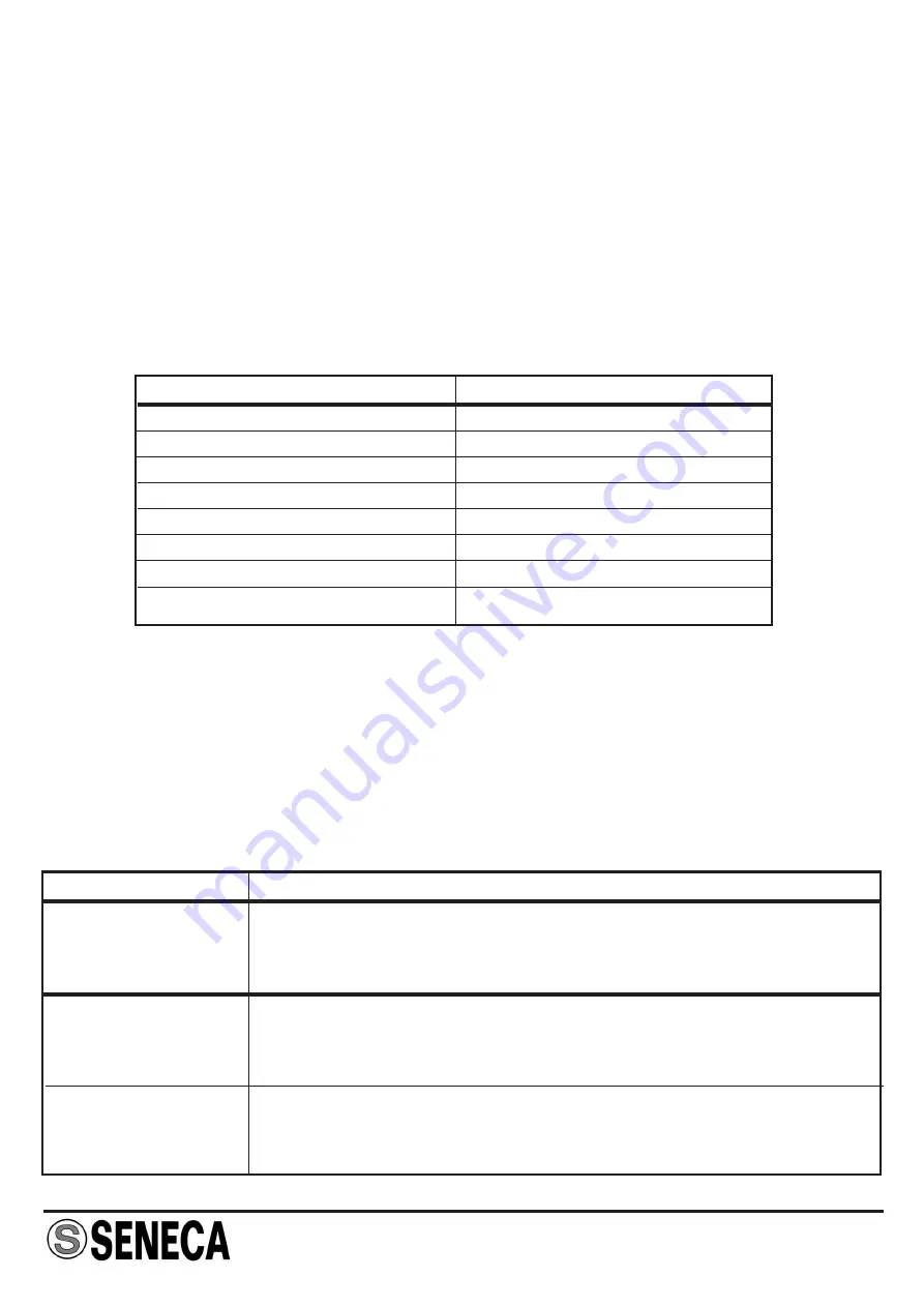
The device usually stays with both its communication ports in reception state (idle
status); the first transition (character) detected at one of the ports enables the
corresponding communication channel, while the opposing port becomes the data
outlet by repeating the stream (data flow) received on the first. Whenever the data flow
is interrupted, after a period of time depending on the communication speed set, the
device returns to its previous state of reception on both ports (idle status).The time for
return to idle status is usually around 1.5 characters starting from the reception line's
last active status; in any case however, a different period of time can be selected
whenever required by protocol. The table below indicates switching times on the basis
of the transmission speed set:

Description of operation

Two modules can be used as insulator or repeater for a Full-Duplex connection. In this
case, it is useful that the module installed on the master's Tx line inhibit communication
direction by selecting either the X->Y direction or the Y->X direction; although switching
both dip-switches ON does not cause malfunctions, it inhibits the device with both ports
in transmission.

Signalling by LED on the front panel

LED

Meaning

Green Led
on X side

Green Led
on Y side

Central Green Led

A blink of the LED when the device is turned on indicates the
presence of voltage.

Flashing: data presence at X-port.
Steady: inverted connection at X port or  X -> Y direction
inhibition enabled.

Flashing: data presence at Y-port.
Steady: inverted connection at Y port or Y -> X  direction
inhibition enabled.

MI00101

-4

-E

N

Summary of Contents for K107A

Page 1: ... dip switch They differ in the type of interface present on the X side K107A RS485 K107B RS232B Technical features Power supply Consumption 19 2 30 Vdc max 22 mA at 24 Vdc under normal operating conditions Type Capacity Terminator Protection K107A RS485 K107B RS232B 32 standard nodes for K107A Yes for K107 A No for K107B Up to 30 Vdc RS485 half duplex 32 standard nodes Yes Up to 30 Vdc Type Capaci...

Page 2: ...ion industrial environment EN61000 6 2 2005 electromagnetic immunity industrial environment EN61010 1 2001 safety All circuits must be insulated from the other circuits under dangerous voltage with double insulation The power supply transformer must comply with EN60742 Insulated transformers and safety transformers Notes Use with copper conductor Use in Pollution Degree 2 Environment Power Supply ...

Page 3: ...erent period of time can be selected whenever required by protocol The table below indicates switching times on the basis of the transmission speed set Description of operation Two modules can be used as insulator or repeater for a Full Duplex connection In this case it is useful that the module installed on the master s Tx line inhibit communication direction by selecting either the X Y direction...

Page 4: ...whenever no such indication is provided it means that the DIP switch is set in 0 OFF X Y DIRECTION INHIBITION 1 SW1 Disabled Enabled Y Terminator 2 SW1 Disabled Enabled 115200 57600 38400 19200 9600 4800 2400 1200 Y X DIRECTION INHIBITION 6 SW1 Disabled Enabled X Terminator only for the K107A 7 SW1 Disabled Enabled Polarizer only for the RS232 of the K107 B 8 SW1 Disabled Enabled When installed th...

Page 5: ...ards 1 Apply leverage using a screwdriver as shown in the figure 2 Rotate the module upwards Inserting the module in the rail Removing the module from the rail Using the K BUS connector 1 Compose the K BUS connectors as required in order to obtain the number of positions necessary each K BUS permits the insertion of no 2 modules 2 Insert the K BUS connectors in the rail by positioning them on the ...

Page 6: ...g the need to connect power supply to each module The bus can be supplied from any of the modules the total absorption of the bus must be less than 400 mA Higher absorption values can damage the module An appropriately sized fuse must be connected in series to the power supply 3 Using the K BUS connector accessory for the distribution of the power supply to the modules via bus connector and the K ...

Page 7: ...s recommended and especially whenever the length of the connections is greater than 3 m 1 5 6 7 8 2 3 4 POWER SUPPLY Y SIDE X SIDE A B 1 5 6 7 8 2 3 4 POWER SUPPLY Y SIDE X SIDE SCH A B SCH K107B Serial port electric connections X side serial port half duplex RS232 1 5 6 7 8 2 3 4 POWER SUPPLY Y SIDE X SIDE SCH Tx out Rx in 1 5 6 9 PC Serial Port MI00101 4 EN ...

Page 8: ... correctly you will help prevent potential negative consequences to the environment and humanhealth whichcouldotherwisebecausedbyinappropriatedisposalofthisproduct Therecyclingof materials will help to conserve natural resources For more detailed information about the recycling of this product please contact your local city office waste disposal service or thè retail store where you purchasedthisp...

Reviews: