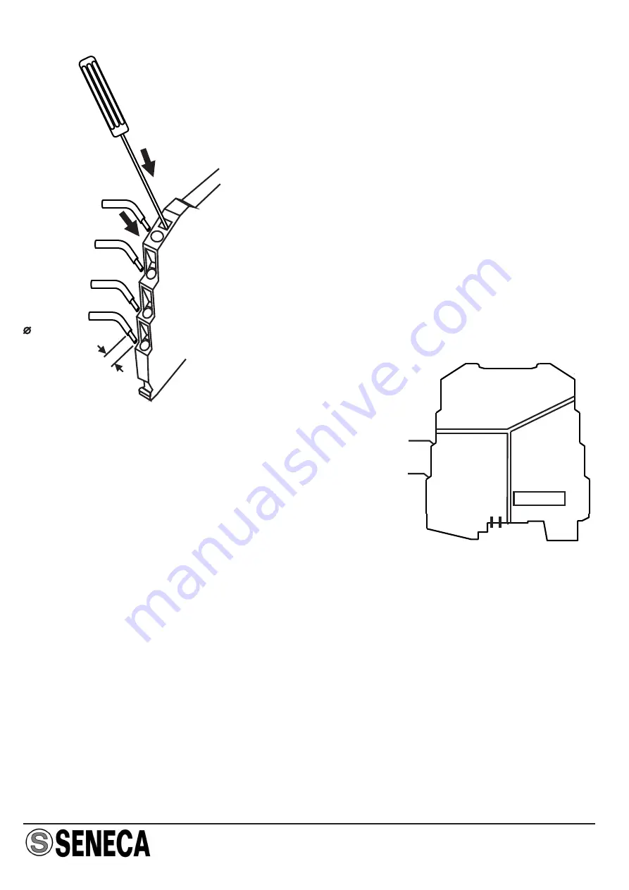
background image

ENGLISH - 6/8

8 mm

0,2..2,5 mm

2

Electrical Connections

The module has been designed for spring-type terminal
electrical connections.
Proceed as follows to make the connections:
1 - Strip the cables by 0.8 mm
2 - Insert a screwdriver in the square hole and press it

until the cable lock spring opens.

3 - Insert the cable in the round hole.
4 - Remove the screwdriver and make sure that the cable

is tightly fastened in the terminal.

Power supply

There are various ways to provide the K Series
modules with power.

1 - Direct power supply to the modules by
connecting 24 Vdc power supply directly to
Terminals 7 ( + ) and 8 ( - ) of each module.

2 - Using the K-BUS connector accessory for the distribution of the power supply to the
modules via bus connector, in this way eliminating the need to connect power supply to
each module.
The bus can be supplied from any of the modules; the total absorption of the bus must be
less than 400 mA. Higher absorption values can damage the module. An appropriately
sized fuse must be connected in series to the power supply.

3 - Using the K-BUS connector accessory for the distribution of the power supply to the
modules via bus connector and the K-SUPPLY accessory for the connection of the power
supply.
The K-SUPPLY accessory is a 6.2 mm wide module that contains a set of protections
designed to protect the modules connected via bus against over-voltage loads.
The bus connector can be provided with power using the K-SUPPLY module if the total
absorption of the bus is less than 1.5 A. Higher absorption values can damage both the
module and the bus. An appropriately sized fuse must be connected in series to the power
supply.

1

5

6

7

8

2

3

4

POWER
SUPPLY

Y SIDE

X SIDE

19.2..30 Vdc

+

-

MI00101

-4

-E

N

Summary of Contents for K107A

Page 1: ... dip switch They differ in the type of interface present on the X side K107A RS485 K107B RS232B Technical features Power supply Consumption 19 2 30 Vdc max 22 mA at 24 Vdc under normal operating conditions Type Capacity Terminator Protection K107A RS485 K107B RS232B 32 standard nodes for K107A Yes for K107 A No for K107B Up to 30 Vdc RS485 half duplex 32 standard nodes Yes Up to 30 Vdc Type Capaci...

Page 2: ...ion industrial environment EN61000 6 2 2005 electromagnetic immunity industrial environment EN61010 1 2001 safety All circuits must be insulated from the other circuits under dangerous voltage with double insulation The power supply transformer must comply with EN60742 Insulated transformers and safety transformers Notes Use with copper conductor Use in Pollution Degree 2 Environment Power Supply ...

Page 3: ...erent period of time can be selected whenever required by protocol The table below indicates switching times on the basis of the transmission speed set Description of operation Two modules can be used as insulator or repeater for a Full Duplex connection In this case it is useful that the module installed on the master s Tx line inhibit communication direction by selecting either the X Y direction...

Page 4: ...whenever no such indication is provided it means that the DIP switch is set in 0 OFF X Y DIRECTION INHIBITION 1 SW1 Disabled Enabled Y Terminator 2 SW1 Disabled Enabled 115200 57600 38400 19200 9600 4800 2400 1200 Y X DIRECTION INHIBITION 6 SW1 Disabled Enabled X Terminator only for the K107A 7 SW1 Disabled Enabled Polarizer only for the RS232 of the K107 B 8 SW1 Disabled Enabled When installed th...

Page 5: ...ards 1 Apply leverage using a screwdriver as shown in the figure 2 Rotate the module upwards Inserting the module in the rail Removing the module from the rail Using the K BUS connector 1 Compose the K BUS connectors as required in order to obtain the number of positions necessary each K BUS permits the insertion of no 2 modules 2 Insert the K BUS connectors in the rail by positioning them on the ...

Page 6: ...g the need to connect power supply to each module The bus can be supplied from any of the modules the total absorption of the bus must be less than 400 mA Higher absorption values can damage the module An appropriately sized fuse must be connected in series to the power supply 3 Using the K BUS connector accessory for the distribution of the power supply to the modules via bus connector and the K ...

Page 7: ...s recommended and especially whenever the length of the connections is greater than 3 m 1 5 6 7 8 2 3 4 POWER SUPPLY Y SIDE X SIDE A B 1 5 6 7 8 2 3 4 POWER SUPPLY Y SIDE X SIDE SCH A B SCH K107B Serial port electric connections X side serial port half duplex RS232 1 5 6 7 8 2 3 4 POWER SUPPLY Y SIDE X SIDE SCH Tx out Rx in 1 5 6 9 PC Serial Port MI00101 4 EN ...

Page 8: ... correctly you will help prevent potential negative consequences to the environment and humanhealth whichcouldotherwisebecausedbyinappropriatedisposalofthisproduct Therecyclingof materials will help to conserve natural resources For more detailed information about the recycling of this product please contact your local city office waste disposal service or thè retail store where you purchasedthisp...

Reviews: