MI00205-7-EN
INSTALLATION MANUAL
4/4
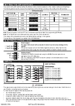
SETTING THE DIP-SWITCHES
The position of the DIP-switches defines the Modbus communication parameters of the module: Address and Baud Rate
The following table shows the values of the Baud Rate and the Address according to the setting of the DIP-switches:
Note:
When DIP switches 3 to 8 are OFF, the communication settings are taken from programming (EEPROM).
Note 2
:
The RS485 line must be terminated only at the ends of the communication line.
DIP-Switch status
SW1 POSITION
BAUD
RATE
SW1 POSITION
ADDRESS
POSITION
TERMINATOR
1 2 3 4 5 6 7 8
3 4 5 6 7 8
10
9600
#1
Disabled
19200
#2
Enabled
38400
#...
57600
#63
From
EEPROM
From
EEPROM
The settings of the dip-switches must be compatible with the settings on the registers.
The description of the registers is available in the USER MANUAL.
ELECTRICAL CONNECTIONS
2
3
-
Vac/Vdc
+ Vac/Vdc
1
Power supply:
The upper limits must not be exceeded in order to avoid serious damage to the
module
.
If the power supply source is not protected against overload, a safety fuse must be
installed in the power supply line with a value suitable to what the situation requires.
ModBus RS485
Connection for RS485 communication using the MODBUS master system as an
alternative to the Z-PC-DINx bus.
N.B.: The indication of the RS485 connection polarity is not standardised and in some
devices may be inverted.
INPUTS
1
11
12
7
8
9
10
#1
#2
#3
#4
#5
+
Z-D-IN-1
16V
~
1
11
12
7
8
9
10
1
11
12
7
8
9
10
PNP
NPN
#1
#2
#3
#4
#5
#1
#2
#3
#4
#5
R=1k5
1k5
1k5
1k5
1k5
INPUT SETTINGS:
Default settings:
Input #1: 0 – 100 Hz (16BIT)
Input #2: 0 – 100 Hz (16BIT)
Input #3: 0 – 100 Hz (16BIT)
Input #4: 0 – 100 Hz (16BIT)
Input #5: 0 – 100 Hz (16BIT)
Input #5 can be set as totalizer:
Input #5: 0 – 10 kHz (32BIT)
GND
B
A
4
5
6
-
+
The upper power supply limits must not be exceeded, as this might cause serious damage to the module. Switch the mod-
ule off before connecting inputs and outputs.
To meet the electromagnetic immunity requirements:
•
use shielded signal cables;
•
connect the shield to a preferential instrumentation earth system;
•
a fuse with a MAX. rating of 0,5 A must be installed near the module.
•
separate shielded cables from other cables used for power installations (inverters, motors, induction ovens, etc...).
•
make sure that the module is not supplied with a supply voltage higher than that indicated in the technical specifications
in order not to damage it.
ATTENTION


