USER MANUAL – Z-GPRS2-SEAL / Z-LOGGER-SEAL
136
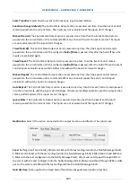
Event control states:
Click for select the actual state from 1 to 6 (S1 to S6).
Change Control State:
Click for pass to next/previous state from 1 to 6 (S1 to S6)
State Reset:
Press the state reset button for clean the actual state logic configuration
Actual State:
Show the actual state from S1 to S6
Input Condition Values:
Are the inputs values that active the actual state logic configuration.
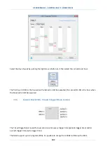
Select from:
= don’t care, this input is not evaluated
= this input must be True (1)
= this input must be False (0)
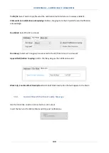
Logic state Representation:
It’s a logic electrical representation, the input condition enters into an AND
port, the result value is connected to one of the outputs. Only one output can be connected in one State.
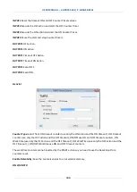
Output Selector:
Chose to which output the AND port output must be connected.
Add/Remove Inputs:
Add/Remove EC inputs from 1 to 4.
Add/Remove Outputs:
Add/Remove EC inputs from 1 to 6.


