USER MANUAL – Z-GPRS2 / Z-LOGGER
15
4.
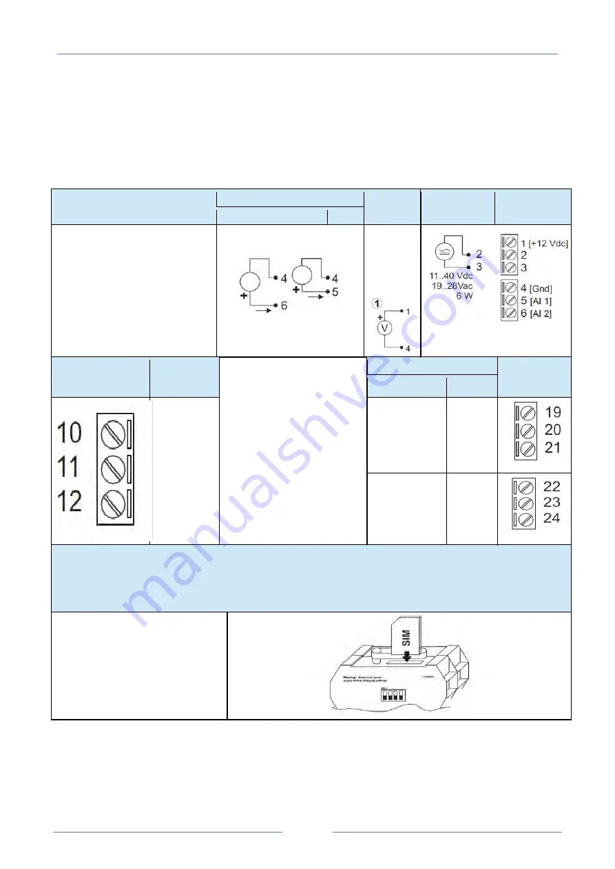
Connections
DESCRIPTION
Analog inputs
Auxiliary
voltage
Power supply
Terminals
V/I [2]
V/I [1]
Set power or current analog inputs using
Easy Z-GPRS2/Z-Logger installation
software.
Settable 0..10 Vdc 0..20 mA
12..15 Vdc
@40 mA
from
module
Terminals
RS485
communication
port #2
Digital outputs
DO[2]
DO[1]
GND, RS485 Port
#2
A, RS 485 Port
#2
B, RS 485 Port
#2
N. Open
Shared N.
Closed
N. Open
Shared
N. Closed
SIM CARD (Z-GPRS2 ONLY)
SIM, Insertion via tray connector.
If correctly inserted, the SIM
protrudes 4.5 mm from the front.
Summary of Contents for Z-GPRS2
Page 8: ...MANUALE UTENTE Z GPRS2 Z LOGGER 8...
Page 72: ...MANUALE UTENTE Z GPRS2 Z LOGGER 72...
Page 165: ...USER MANUAL Z GPRS2 Z LOGGER 73...


