background image

Operation 


20


Buttons and menu 

The AQUACULTURE|CONTROL is operated by the user via the buttons on the front. With the 
navigation buttons (

BACK and HOME) you can navigate through the menu.  

To change the displayed view from the filter status to the sensor values (the number in the 
center circle show the SENSOR plug number) press  

 or 

. To view the status of an output 

port, select the corresponding sensor plug, e.g. plug 1 and press 

. You can then also change 

to the other output ports with 

 or 


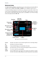
Fig. 9: Keypad of the AQUACULTURE|CONTROL. 


Cursors:  

With the cursor buttons you can move through the menu and change settings.. 

OK:         With OK you confirm your selection. 

BACK: 

The button BACK brings you one level back in the menu. 

HOME:  

 By pressing home, the home screen will be displayed and you exit the menu. 

MENU:  

 The menu is opened by pressing MENU. 

GRAPH:  

With the GRAPH-button, the stored sensor readings are visualized as a xy plot. 
With the cursor buttons 

 and 

 you can switch between the measured data 

Stop-Key

Start filter

backwash

Filtermotor

on / o ff

Shortcut to menu

230 V plugs

Shortcut to menu

Sensors

Shortcut to menu

Output ports

(actuator out)

Menu

Graphs /

Information /

History

Navigation-

keys

Display

Serial number

Summary of Contents for AQUACULTURE AQC-A1-333-150

Page 1: ......

Page 2: ... 300 Producer SENECT GmbH Co KG An 44 No 11 76829 Landau Germany Important note Please read this manual carefully and store it so that you can use it later Read the warning and safety notes attentive More information and latest software releases or documents can be downloaded from www senect de Further information application descriptions and answers to frequently asked questions can be also found...

Page 3: ...rum filter with the AQUACULTURE CONTROL 11 Using the AQUACULTURE CONTROL to switch outputs as a function of sensor measurements Short version 16 Controlling the drum filter with the AQUACULTURE CONTROL Short version 17 Operation 19 Display and symbols 19 Buttons and menu 20 The Menu 22 Filter settings 26 Sensor Menu 30 Menu output ports and 230 V AC plugs 32 Description of the major output functio...

Page 4: ... Since it is an electric product the common prerequisites for a safe instrument usage must be fulfilled The device must be operatated with 230 V AC 50 Hz Ensure that all cables are installed safely so that no obstacles for persons are built and all Mount all cables and electric devices protected against direct environmental impacts like overheating by direct sunlight and water Even if the product ...

Page 5: ...rvised trained in the operation of the device able to operate the device safely and if they understand potential risks resulting from the operation It is for children or persons with limited physical sensorial or cognitive ability not allowed to perform any maintenance works Please store this manual We suggest the storage a copy of the manual in the vicinity of the device Technical and optical cha...

Page 6: ...pending on the sensor readings or send alarm message if the control unit is connected to the internet At its actuator output ports 24 V DC actuators like valves or fish feeders can be connected directly Also actuators which can be controlled via 4 20 mA or 0 10 V control signals can be controlled directly Actuators with 230 V AC can be switched with the actuator ports by using the optional PowerSw...

Page 7: ...al Note Please check directly after delivery that the package is not destroyed or damaged or was opened before Please check also that all parts as listed above are included If anything is missing or broken please contact us as soon as possible within 14 days Unfortunately we cannot accept later information of damage which happened during the transport Installation and start up Choose a place for y...

Page 8: ...ng parts and dimensions of the drill holes for the mounting of the AQUACULTURE CONTROL Fig 2 Sensor and actuator ports of the AQUACULTURE CONTROL Pro The AQUACULTURE CONTROL Basic is equipped without the upper row SENSOR 4 6 and OUT 4 6 ...

Page 9: ...cables safely to the AQUACULTURE CONTROL remove the protection cap from the sensor input port and connect the sensor plug to the blue marked SENSOR input 3 Switch on the AQUACULTURE CONTROL and set the desired settings To switch the output ports you have to assign a function to the selected output port Fig 3 View from the bottom side of the AQUACULTURE CONTROL Note Changing languages can be easili...

Page 10: ...0 are reached the addition of oxygen shall be stopped Go to the menu MENU Output Ports Plug 1 and set Function Sensor Control a new submenu appears when you go back in the menu In the submenu Sensor Control set o Control Parameter O2 a s o Sensor Plug 1 o Start value 95 o Stop value 100 o Max Duration 00 00 00 o Break Time 00 00 In the submenu Output signal set o Polarity Low Active the output is ...

Page 11: ...systems this is typically before the filter or in the pre chamber of the filter Please do not insert the water level sensor deeper than 2 5 m and ensure that it is well fixed and at a location with low direct currents Read also the instructions of the water level sensor manual Connect the water level sensor cable to the AQUACULTURE CONTROL e g with SENSOR 1 see Fig 2 If you are using a second wate...

Page 12: ...Getting started 12 Fig 4 Connecting an open channel drum filter and a boxed drum filter Please note that the filter motors here are controlled by the high power acuator output port OUT 3 ...

Page 13: ... for other consumers like a spray pump or can be connected to actuator output ports via the optional Power Switch 24 230 Art No 3100 Note here that all functions where the motor speed is controlled by the AQUACULTURE CONTROL do not work because there is just an on off switching of the filter motor possible These functions are Intensive cleaning programme Soft motor start High pressure cleaning mod...

Page 14: ... specifications of the AQUACULTURE CONTROL 230 V OUT 1 230 V AC max 1800 W 230 V OUT 3 230 V AC max 900 W Plug the spray pump connector into the plug 230 V OUT 1 and the connector of the circulation pump to the plug 230 V OUT 3 see To operate a drum or belt filter correctly it is necessary to connect the filter motor and spray pump according to the specifications of the filter producer Every drum ...

Page 15: ...the normal screen and exits the menu If your filter is used in a pumped system select in the Filter Settings as Filter Mode Pumped System If you are operating the filter in gravity mode select Gravity System If you are using a 230 V AC filter motor connected to a 230 V main plug select in the menu at 230 V Plug 230 V Plu X the function Filter Motor If you are using a 230 V AC filter motor connecte...

Page 16: ...pray jet backwash pump to the AQUACULTURE CONTROL assign the function Spray pump to the corresponding 230 V plug If you have it connected via an PowerSwitch or VFD at one of the actuator output ports assign the function Spray pump to this port Clean the filter by pressing the button CLEAN FILTER After the cleaning process check the water level in your system If the water level is correct you have ...

Page 17: ...filter backwash by the difference in water level install both sensors one in the pre chamber one in the filter chamber see Fig 4 3 Connect the filter motor cable the spray pump the cover switch and the circulation pump with your AQUACULTURE CONTROL a If you are using a VFD connect the motor to the VFD connect the green marked actuator cable of the VFD to the AQUACULTURE CONTROL to OUT 1 and plug t...

Page 18: ... ready for operation Please note that the filter backwash water levels refer to the referenced water level while the alarm settings of the sensor refer to the absolute water level Fig 7 Relative water level vs absolute water level reference zero level absolute water level used for alarming e g 48 cm relative water level used for filter operation e g 5 cm ...

Page 19: ...ction symbols which display the current running actions or modes of operation The action symbols are Alarm active Pause release with STOP Pin code active unit blocked Circulation pump on Filter cleaning WLAN Not connected WLAN connected but not internet access WLAN Connected with network WLAN Configuration mode active WLAN Update available Fig 8 The display of the AQUACULTURE CONTROL ...

Page 20: ...of the AQUACULTURE CONTROL Cursors With the cursor buttons you can move through the menu and change settings OK With OK you confirm your selection BACK The button BACK brings you one level back in the menu HOME By pressing home the home screen will be displayed and you exit the menu MENU The menu is opened by pressing MENU GRAPH With the GRAPH button the stored sensor readings are visualized as a ...

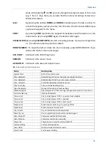
Page 21: ...ption of the history entries Entry Description System Start Start of the control unit Man Backwash Backwashing started manually by pressing the button Sens Backwash Backwashing started by sensor measurements Sens Forced B Forced backwashing started by sensor Time contr Bw Time controlled backwashing Abort backwash Manual interruption of backwashing Modus changed Operating mode of filter settings c...

Page 22: ...ched off Feeding Feeder active No Feeding Feeding cancelled due to environmental parameters e g O2 temp Cover opened Cover switch recognizes open cover Cover closed Cover switch detects closing of cover Output Alarm Alarm on output Output Ok Alarm on output cleared Sensor Error Error at sensor Sensor Alarm Sensor measurements above or below alarm thresholds Sensor Ok Sensor values again in normal ...

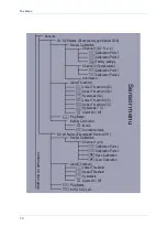
Page 23: ...1 Dry run Protection 2 only pumped system Backwash Parameter Backwash Duration Pre flushing time Post flushing time Cleaning Pause Forced Clean Cycle Intensive Cleaning Interval Duration Motor Speed Motor Speed Eco Mode Dauer Eco Mode Alarm Mode Deactivate Forced Clean Cycl Service Interval Service Interval High clean int Filter Menu continued on next page Selection selected factory settings not s...

Page 24: ... Point 1 Calibration Point 2 Information Alarm Threshold Lower Threshold O2 Upper Threshold O2 Hysteresis O2 Lower Threshold C Upper Threshold C Hysteresis C Alarm On Off Plug Name Salinity Correction Mode Correction Value S2 pH Name Example pH Sensor XR1 Sensor Calibration Channel 1 pH Calibration Point 1 Calibration Point 2 Save Calibration Load Calibration Alarm Threshold Lower Threshold Upper ...

Page 25: ...ling Time controlled Operating Time Start Time Stop Time Alarm Handling Off Turn output off Turn output on Output Coupling Plug Mode Sensor Control Control Parameter Sensor Plug Start value Stop Value Max Duration Break Time If Error Output Signal Output strength Start up Duration Polarity Switch on for Plug Name Hour meter Menu output ports 123 123 123 123 123 123 123 123 123 123 123 123 continue...

Page 26: ...an choose the operation mode Automatic mode means that based on the clogging of the filter mesh indicated by the measurements of the water level sensor the cleaning is initiated In the Time controlled mode the filter is cleaned in regular time intervals The High Press Cleaner mode lets the filter motor run continuously but slow without activating the spray pump This mode is handy when the filter m...

Page 27: ...s opened Additionally when the 230 V plug 2 is defined as UVC lamp it will be also switched off immediately 4 Cover Sw EBF In case the cover switch is set to EBF which means Endlosbandfilter or continuous belt filter a backwashing will not be interrupted when the cover is opened The UVC on 230 V plug 2 however will be switched off Water level All water level related parameters are system specific ...

Page 28: ...e duration how long the spray pump should stay activated after the filter motor stops Cleaning pause The cleaning pause defines the minimal temporal distance between two filter cleaning events This break prevents from water loss associated from too man cleaning events But in case the water level drops further towards the emergency level the filter flushes despite there is a cleaning pause This fun...

Page 29: ...water level sensor initiates the cleaning only the filter motor is activated for a short time to bring the until then unused filter mesh into the water By monitoring the water level the AQUACULTURE CONTROL will decide when the next full cleaning is necessary In this menu item you can set how long every partial rotation of the drum should last Alarm The alarm mode specifies when you will be alarmed...

Page 30: ...vel Select Pre chamber when the cleaning should be started by a water level increase If your are using two water level sensors and you have set both positions for the two sensors the flushing is induced by the difference in water level between both sensors To refill a tank or pond you have to place the probe in the according location e g in the pond and select Refill Sensor as position If you want...

Page 31: ...ould be calibrated regularly to achieve best accuracy In this menu item you can calibrate either the oxygen sensor signal or the temperature signal of the O2S Please choose which parameter should be calibrated e g O2 a s for calibrating the oxygen signal All calibrations are programmed as 2 point calibrations where also only one point can be changed This is for example important if you want to cal...

Page 32: ...for this sensor Plug name With plug name you can give the sensor a name of max 8 characters which will be displayed in the SENECT Control App Salinity correction Since the oxygen saturation concentration depends on the salinity of the water the SENECT control can correct for the effect of salinity Therefore you can either enter a specific salinity Mode Correction value or connect a conductivity se...

Page 33: ...s active when the filter motor is activated By using output signals like 4 20 mA you can for example also control variable frequency drives for using 380 V motors To control the motor speed via 4 20 mA and switching it on and off with 24 V DC please select as Additional function Var Frequency Drive see also page 13 Spray pump Defined as Spray pump the output is activated as defined in the filter s...

Page 34: ...tion the saturation increases and if 100 are reached the output is switched off again Application example Stopp Start The opposite example of this is the control of a pump which empties a pump sump Here the water level is the sensing parameter and to output a pump is connected The pump should be switched on when the water exceeds a threshold let s say 30 cm and switched off when there is only 10 c...

Page 35: ...on manually you can see the feed amount per event below the duration time Daily increase Since fish grow with time and need therefore more feed per day the feed control can automatically increase the daily amount of feed Insert here the increase rate in Environ based feed Under this menu item several environmental parameter based functions are included Low O2 Protection In case the oxygen concentr...

Page 36: ...nt and when you adjust the duration of the feeding you can see directly the feed weight which corresponds to the duration The function feeder creates a dynamic submenu where additional features Time control which are here the feeding times Output signal etc like previously described can be set Hint If you want to increase the oxygen level prior to feeding select the output port of the sensor contr...

Page 37: ...ff Therefore one connected sensor must be defined as a case switch Alarm Does one sensor value exceeds the upper threshold or falls below the lower threshold a alarm state is activated and all outputs with alarm coupling or outputs with the function alarm react Here you can for example connect an alarm lamp directly to the output e g the SENECT Alarm lamp VIS LED Depending on the selected function...

Page 38: ...d with the function feeder The desired functionality is now that the aeration should be activated always when the fish feeder is feeding Select at the OUT 1 the additional function Output coupling and refer in plug to OUT 2 Select On if on and the aeration is switched on independent of the sensor control when the feeder is activated The third possible additional function is Time controlled It can ...

Page 39: ...t and end at the first day At the second day it starts 1 min earlier and stops 1 min later Special additional functions If the plug is defined as Filter Motor the special additional function Var freq drive can be used to control variable frequency drive VFD with a 4 20 mA signal and the activation with the 24 V DC signal This function is designed to control 230 V AC and 380 V AC filter motors SENE...

Page 40: ...ur meter To see how long an output was activated you can use the hour meter menu item Here you can set it to zero and from then on there will be displayed in the screen of the corresponding output in the bottom line the hours of activation press in the home screen to switch to the output screens and then until you are the selected output port This function can be for instance be used to estimate e...

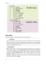
Page 41: ...he Windows and MacOS versions of the app can be downloaded on www senect de app You can change the language of the app under the Settings button Please have the name of the WLAN network SSID Name and the WLAN password ready You need to proceed through the following steps to connect the AQUACULTURE CONTROL to the internet Set the AQUACULTURE CONTROL in WLAN configuration mode Menu WLAN WLAN Configu...

Page 42: ...ion 3 Enter the corresponding dynamic DNS address next chapter port number at delivery 30000 and PIN at delivery 0000 4 Press the button Add device The AQUACULTURE CONTROL can now be operated with your SENECT Control App when your smartphone PC is within the same WLAN network To enable the remote access you need to establish a dynamic DNS connection 1 Activate a DynDNS account e g a MyFritz accoun...

Page 43: ...ernet to Freigaben and select to add a new device Gerät für Freigabe hinzufügen 3 Select at Gerät the AQUACULTURE CONTROL It will be labelled with Senect 101xxxxx where the x denote the serial number of your AQUACULTURE CONTROL ...

Page 44: ...is Andere Anwendung 5 Select as Schema http and type in the port number of the AQUACULTURE CONTROL 30000 as factory setting if you use several SENECT control units each single one must have its own port number You can change it in the menu WLAN Port number ...

Page 45: ...ou can see the dynamic DNS address of the control unit You need this address in the SENECT Control App to establish the remote access To enable the remote access with the SENECT Control App you need to go to the WLAN settings of the control unit in your App Press therefore the button settings Enter the dynamic DNS address without the http and without the port number e g here the 30100 in the field...

Page 46: ... Here you can change it e g to 30001 DHCP For some routers it is necessary to switch DHCP off Here you do this and then set the corresponding network settings manually IP address Gateway DNS Subnetmask WLAN reset If you want to delete the WLAN settings select reset WLAN and confirm with yes Please note that only the network settings and information is cleared Menu System Settings Date Time Set the...

Page 47: ...time steps you want to be reminded e g every 15 min Pin Code Here you can enter a 4 number pin code to protect the AQUACULTURE CONTROL from unauthorized usage Note the pin code so that you unlock the AQUACULTURE CONTROL again and store it at a safe place Device Infos Here you find information about the current device like the version of the firmware or the serial number of you AQUACULTURE CONTROL ...

Page 48: ...NTROL without connected consumers Information about the correct disposal Your device is well packed at delivery Please dispose the packaging material accordingly to the regulations in your country Do not throw the product in the casual litter bin Make sure you are informed about the local disposal regulations and dispose your product accordingly Alternatively you can also send the product back to ...

Page 49: ...following details must be given to guarantee a fast support Detailed error or claim description Information about the use of the AQUACULTURE CONTROL e g system type filter Your contact information The AQUACULTURE CONTROL has a guarantee of 1 year and a warranty of 2 years Furthermore the 377 HBG German law is valid ...

Reviews: