background image

Helping Customers Innovate, Improve & Grow

TempTrackr™ Wireless 

System Kit

Quick Setup Guide and 

Operation Manual

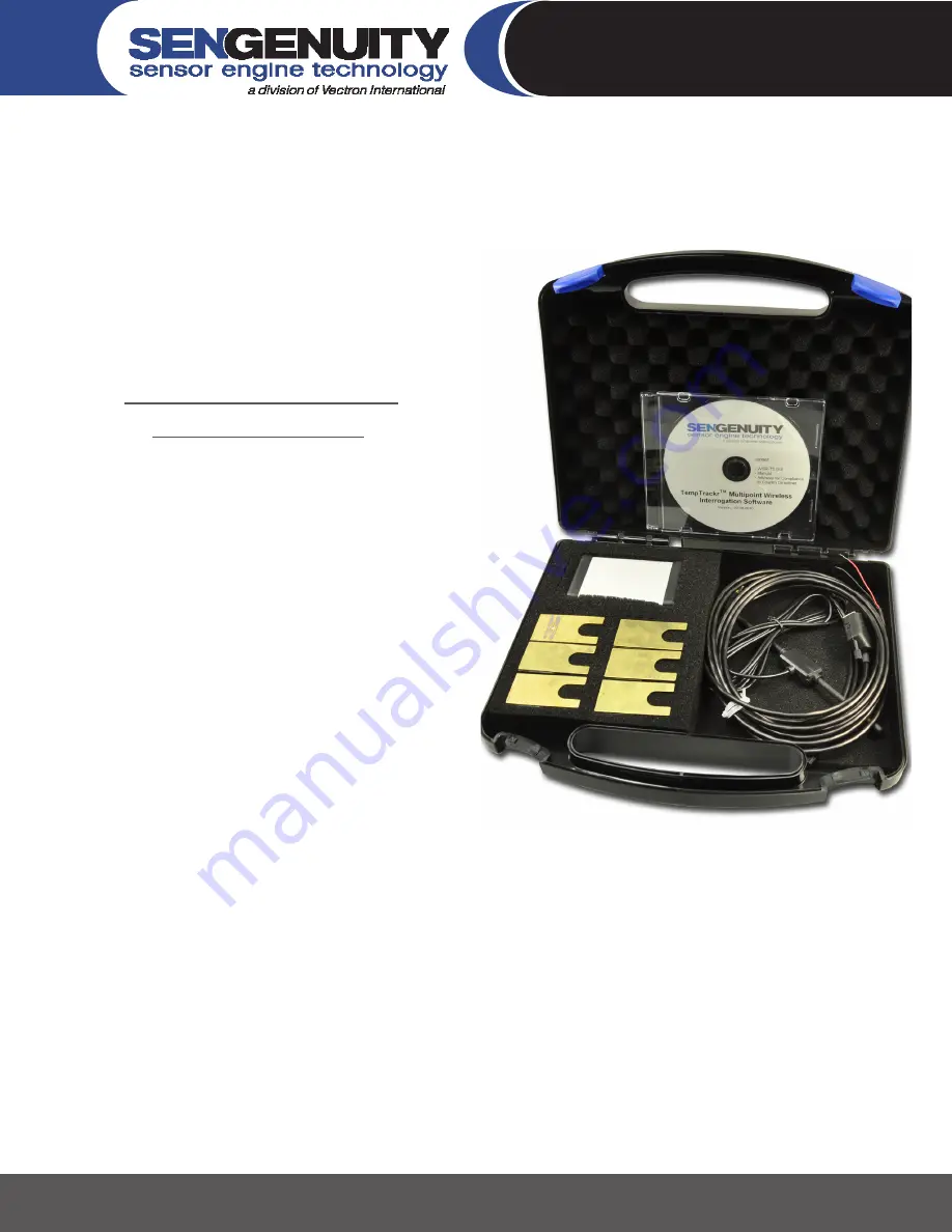
The TempTrackr Multipoint Starter kit includes:

Three or Six wireless temperature sensors

• 

One wireless interrogation unit

• 

One dipole interrogation antenna

• 

One RS232/RS485 cable

• 

One software CD with the TempTrackr™ Wireless

• 


  Interrogation Software

Please  contact  SenGenuity  if  any  item  is  either  missing 

or damaged.  The wireless interrogation unit needs to be 

powered by a 5V±5% DC power-supply.  All temperature 

sensors  are  interrogated  by  one  interrogation  antenna.  

The TempTrackr™ Starter Kit can be setup in three simple 

steps:

267 Lowell Rd, Hudson NH 03051, USA      |      Phone: 1.888.328.7661     |      Fax: 1.888.329.8328      | 


www.sengenuity.com

Install and Configure TempTrackr™ Wireless Interrogation Software

1. 

Setup and connect wireless interrogation unit

2. 

Setup, locate and calibrate wireless sensors

3. 

Summary of Contents for TempTrackr

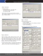
Page 1: ...on Software Please contact SenGenuity if any item is either missing or damaged The wireless interrogation unit needs to be powered by a 5V 5 DC power supply All temperature sensors are interrogated by...

Page 2: ...ngenuity TempTrackr Start the Software from the Windows Start Menu or by double clicking the WSR T2 icon from the directory in which the software has been installed Figure 1 InstallShield Window for T...

Page 3: ...ued Connect the Wireless Interrogation Unit to a power supply 5V 5 DC 350mA as shown in Figure 6 You can now connect the RS232 RS485 cable to your PC laptop Step 2 Step 2 Setup and connect wireless in...

Page 4: ...t should be followed when locating the sensors The minimum distance between two sensors must be 4 inches 10 cm The minimum distance between any given sensor and the interrogation antenna must be 12 in...

Page 5: ...eaders Step 3 continued Select Calibrate from the Sensors Menu to obtain the Calibration Screen Sensors are identified by model numbers that reflect nominal the frequency of each sensor Since the six...

Page 6: ...ise the calibration will be lost if the reader is powered off Press Test VALUE_INTER again Figure 13 shows the results of a successful calibration Figure 13 Calibration procedure FCC version complete...

Page 7: ...nd found to comply with the limits for a Class B digital device pursuant to Part 15 of the FCC Rules These limits are designed to provide reasonable protection against harmful interference in a reside...

Page 8: ...pas l intensit n cessaire l tablissement d une communication satisfaisante Le pr sent metteur radio identifier le dispositif par son num ro de certification ou son num ro de mod le s il fait partie du...

Reviews: