Page 11
Copyright © 2020 Sensata Technologies, Inc.
Rocker
Step 1: Choose Letter For Body Color
B:
Black
G:
Gray
W:
White
R:
Black w/ Handle guard
S:
Gray w/ Handle guard
T:
White w/ Handle guard
Example: “W...”For White Rocker Body
(Rocker Style)
Step: 2: Choose Handle Combinations
Without Illumination Basic Handle Color
(w/o Markings)
01:
Black
02:
Red
06:
White
07:
Orange
108:
Clear w/4-8 Vdc Green LED
109:
Clear w/8-16 Vdc Green LED
121:
Transparent Red w/Neon (Note A)
123:
Transparent Red w/Red LED (Note B)
124:
Transparent Red w/Red LED 4-8 Vdc
125:
Transparent Red w/Red LED 8-16 Vdc
161:
Translucent White w/Neon (Note A)
162:
Translucent White w/ Green Glow Neon (Note A)
171:
Transparent Amber w/Neon (Note A)
181:
Transparent Smoke Gray w/Neon (Note A)
182:
Transparent Smoke Gray w/Green Glow Neon (Note A)
183:
Transparent Smoke Gray w/Red LED (Note B)
184:
Transparent Smoke Gray w/4-8 Vdc Red LED
185:
Transparent Smoke Gray w/8-16 Vdc Red LED
187:
Transparent Smoke Gray w/Green LED (Note B)
188:
Transparent Smoke Gray w/4-8 Vdc Green LED
189:
Transparent Smoke Gray w/8-16 Vdc Green LED
Example: “-W124” If you prefer NO markings, then your handle decision is now complete.
Step 3: Choose Handle Markings
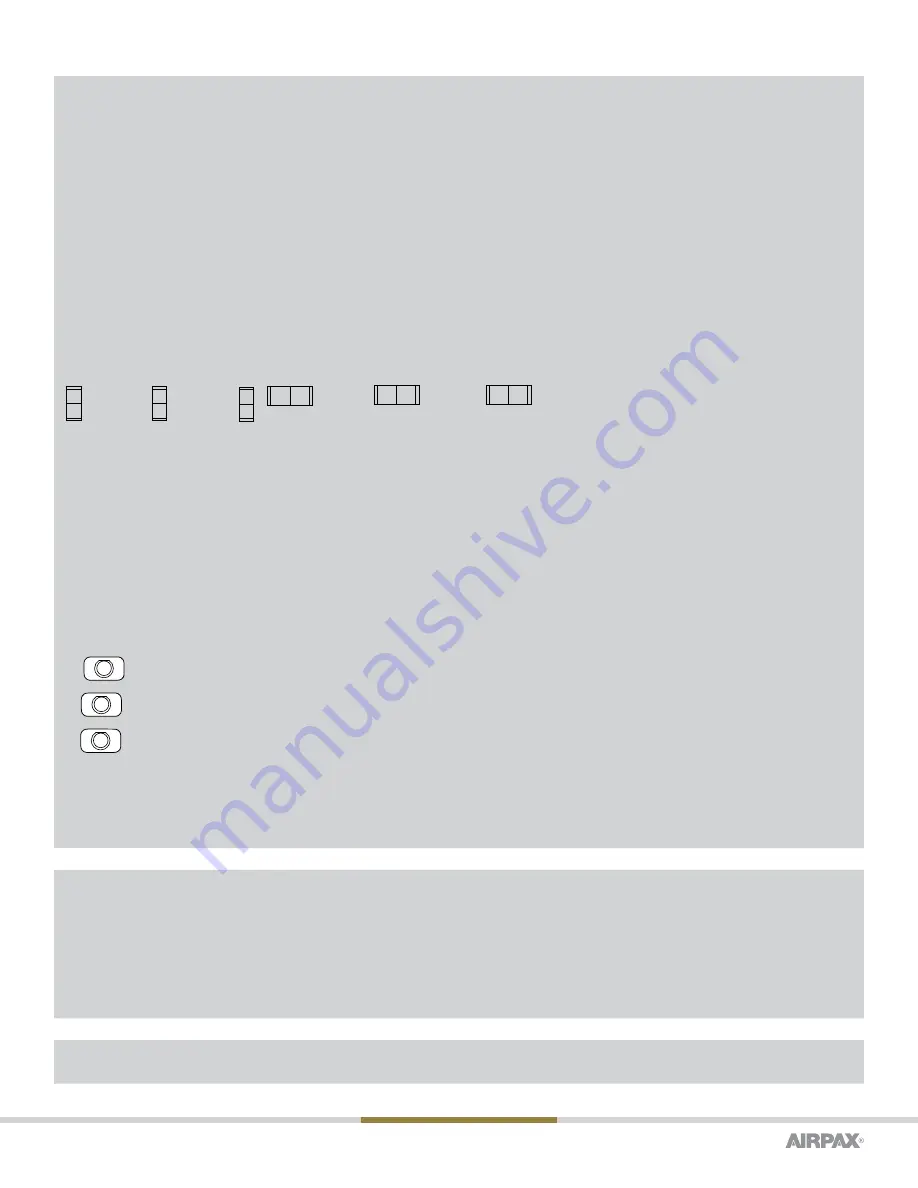
Marked For Vertical Mount-After choice of 3
digit number in step 2 above.
Add “
CV
”
for Combined
markings .
ON
I
O
OFF
Add “
IV
”
for Intíl.
markings .
I
O
Add “
EV
”
for English markings.
Example: "-W124EV "
ON
OFF
Marked For Horizontal Mount-After choice of 3 digit number in step 2 above.
ON
I
Add “
CH
”
for Combined
markings .
Add “
IH
”
for Internationa l
markings.
O
Add “
EH
”
for Englis h
markings .
Example “-W06EH ”
OFF
O
ON
OFF
I
If you have chosen a handle from this table, your 4th Decision and yourcatalog part number are now complete
(except if you require “-S” screwterminal option from the 5th Decision Table.)
Paddle (T) Handle Color
-01:
Black
-02:
Red
-03:
Yellow
-04:
Green
-05:
Blue
-06:
White
If you have chosen a handle from this table, your 4th Decision is now
complete except for hardware options in 5th Decision Table
Push-Pull (PP, CPP and CPR)
-XX:
-XX No button markings desired (not available for CPP & CPR)
-OA:
LINE
5
Marked buttons available for these amperages
-OB:
LINE
5
0.1
.25
0.5
.75
1
2.5
5
7.5
10
15
17.5
20
-OC:
LINE
5
If you have chosen a handle from this table, your 4th Decision & your catalog PN are now complete (except if you require “-S”
screw terminal option from the 5th Decision Table.)
Push-to-Reset (PR)
-XX:
No Button Markings Only
If you have chosen a handle from this table, your 4th Decision and your catalog PN are now complete (except if you require “-S” screw terminal
option from the 5th Decision Table.)
Hardware & Accessories (Notes C and D)
Group I
Group II (Indicator Plate)
Group V (Screw Terminal Options)
-00:
No Outer Hardware Desired
-10:
Black Knurled Nut
-11:
Bright Nickel Knurled Nut
-A:
Vertical Mount (Off/On & O/I)*
-C:
SAE 8-32, Upturned Lugs (Tabs) Straight Terminal
-D:
SAE 8-32, Bus-Type Connect (Flat) Straight Terminal
-F:
M4, Upturned Lugs (Tabs) Straight Terminal
-H:
M4, Bus-Type Connect (Flat) Straight Terminal
-20:
Black Panel Dress Nut
-21:
Bright Nickel Panel Dress Nut
-31:
Bright Nickel Hex Nut
-B:
Horizontal Mount (Off/On & O/I)*
Group III
*Selection of A or B Indicator Plate
required for TUV and CCC.
Please select a screw terminal option if you selected
“S” in Decision 1
-L:
Locking Ring
T, V = TÜV and CCC Approved
The shaded areas denote CCC (if applicable) and CE compliant options.
The V will be added to any part number formed entirely from shaded decisions.
If non-shaded areas are selected, the unit will not be approved, nor CE compliant, but other approvals still apply. 20 amps max rating on units.


