Specification No.: Rev. 11/12/18
Americas
+1 (877) 502 5500
sales.crydom@sensata.com
Europe, Middle East & Africa
+44 (1202) 416170
ssr-info.eu@sensata.com
Asia Pacific
sales.isasia@list.sensata.com
China
+86 (21) 2306 1500
Japan
+81 (45) 277 7117
Korea
+82 (31) 601 2004
India
+91 (80) 67920890
Rest of Asia
+886 (2) 27602006
ext 2808
Page 2
CONTACT US
Copyright © 2019 Sensata Technologies, Inc.
Sensata Technologies, Inc. (“Sensata”) data sheets are solely intended to assist designers (“Buyers”) who are developing systems that incorporate Sensata
products (also referred to herein as “components”). Buyer understands and agrees that Buyer remains responsible for using its independent analysis, evaluation
and judgment in designing Buyer’s systems and products. Sensata data sheets have been created using standard laboratory conditions and engineering
practices. Sensata has not conducted any testing other than that specifically described in the published documentation for a particular data sheet. Sensata may
make corrections, enhancements, improvements and other changes to its data sheets or components without notice.
Buyers are authorized to use Sensata data sheets with the Sensata component(s) identified in each particular data sheet. HOWEVER, NO OTHER LICENSE,
EXPRESS OR IMPLIED, BY ESTOPPEL OR OTHERWISE TO ANY OTHER SENSATA INTELLECTUAL PROPERTY RIGHT, AND
NO LICENSE TO ANY THIRD PARTY TECHNOLOGY OR INTELLECTUAL PROPERTY RIGHT, IS GRANTED HEREIN. SENSATA DATA SHEETS ARE PROVIDED “AS
IS”. SENSATA MAKES NO WARRANTIES OR REPRESENTATIONS WITH REGARD TO THE DATA SHEETS OR USE OF THE DATA SHEETS, EXPRESS, IMPLIED
OR STATUTORY, INCLUDING ACCURACY OR COMPLETENESS. SENSATA DISCLAIMS ANY WARRANTY OF TITLE AND ANY IMPLIED WARRANTIES OF
MERCHANTABILITY, FITNESS FOR A PARTICULAR PURPOSE, QUIET ENJOYMENT, QUIET POSSESSION, AND NON-INFRINGEMENT OF ANY THIRD PARTY
INTELLECTUAL PROPERTY RIGHTS WITH REGARD TO SENSATA DATA SHEETS OR USE THEREOF.
All products are sold subject to Sensata’s terms and conditions of sale supplied at
SENSATA ASSUMES NO LIABILITY FOR APPLICATIONS
ASSISTANCE OR THE DESIGN OF BUYERS’ PRODUCTS. BUYER ACKNOWLEDGES AND AGREES THAT IT IS SOLELY RESPONSIBLE FOR COMPLIANCE WITH
ALL LEGAL, REGULATORY AND SAFETY-RELATED REQUIREMENTS CONCERNING ITS PRODUCTS, AND ANY USE OF SENSATA COMPONENTS IN ITS
APPLICATIONS, NOTWITHSTANDING ANY APPLICATIONS-RELATED INFORMATION OR SUPPORT THAT MAY BE PROVIDED BY SENSATA.
Mailing Address: Sensata Technologies, Inc., 529 Pleasant Street, Attleboro, MA 02703, USA.
• The Elevator Screw option allows the screw and clamp
to be raised out of the mating threads completely. This
provides for the insertion and use of a ring or lug type
wire terminal.
• A #2 Phillips head driver should be used with the
Elevator Screws. If a powered driver is used, avoid
speeds above 500 RPM.
• Cutting threads in the cover plastic as the screw
elevates is key to the elevating feature. It has a finite
life and therefore not recommended to be used more
than 50 times during the product lifetime.
• Do not continue rotating the screw (in the elevating
direction) once it freely rotates at the top of the plastic surface. The Elevator screw is capable of
clearing 0.125 inches between the terminal and the bottom of the screw. Insertion of a terminal or
lug thicker than 0.125 in is not recommended.
• When inserting the terminal ensure that the terminal hole is in line with the screw.
• During tightening, be certain that the terminal is seated flat within the cavity, and that the clamping
washer is secure against the upper surface of the terminal.
• If fork terminations, spade lugs, or stranded wire are used, to prevent improper contact do not raise
the elevator screw out of the mating threads.
(A)
The operation mode is detected during power up. Any changes done to the selector while the unit is
powered will be ignored until next power up
(B)
UL approved rating is the one that intersects at 40°C.
TABLE 5. Recommended Accessories
Hardware Kit
Thermal Pad
Lug Terminal
Heat Sink
Part No.
Thermal
Resistance [ºC/W]
HK8
HS259DR
HS073
HS072
HS053
HS033
HS023
2.5
0.7
0.7
0.5
0.36
0.25
HSP-7
TRM0
TRM6
ACCESSORIES
ELEVATOR SCREW (”W” SUFFIX)
CONSIDERATIONS
GENERAL NOTES
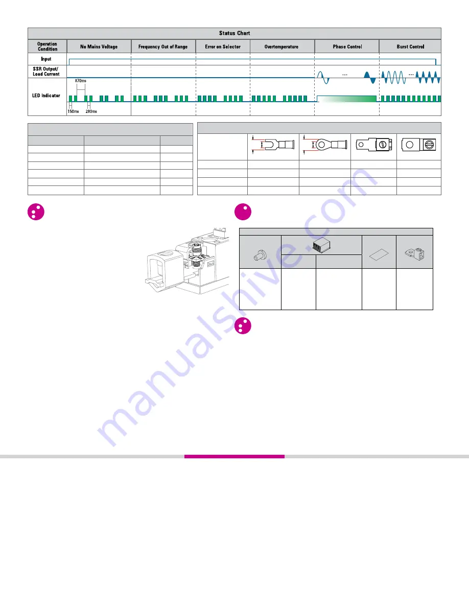
Status
LED Indicator
Flashes twice intermittently
Flashes three times intermittenl y
Flashes four times intermittenl y
Flashes five times intermittenl y
Varying brightness
Varying frequenc y
No Mains Voltage
Frequency Out of Range
Error on Selector
Overtemperature
Phase Control
Burst Control
SSR Output
OFF
OFF
OFF
OFF
ON
ON
Fork LugR
ing Lug
Copper Lug
Copper Lug
Width [W] in (mm)
Terminals
Stud Size Dia [D] (in)
Wire Size AWG
Crydom Part No.
0.45 (11.4)
#8 (0.168)
0.45 (11.4)
#8 (0.168)
TRM0
6-0
TRM6
14-6
W D
W D
fig. 2
Elevator screw
TABLE 3. LED Status
TABLE 4. Compatible Terminals


