


© 2018 Sensata Technologies
3
Control Board Removal and Replacement
Figure 4, Preventing Busbar from Twisting
4.2
Replacing MS/MS-PAE Series Control Boards
Note: If the FET board also needs to be replaced, follow
the information described in the
Large FET Board Removal
and Replacement, Service Instructions: 64-1005
—before
replacing the MS/MS-PAE Series control board.
1. Remove the new control board from its antistatic bag
and place the loose side of the current sense wire
(Figure 7, Item B) back through the LEM.
2. Reconnect the 16–pin ribbon cable connector to the
front of the new control board. Before pushing it in,
ensure it is connected with the red stripe on the ribbon
cable facing toward the rear of the inverter (refer to
Figure 3, Item A for reference) and the connector pins
are aligned correctly.
3. Insert the new control board into the bottom 16-pin
FET board connector. Ensure the connector pins are
aligned correctly before pushing in.
4. Reconnect the negative bus cable and the current
sense wire (running through the LEM) to the negative
FET busbar using the ¼-20 bolt. This connection must
be torqued to 130 in.-lbs. Use a pair of pliers to hold
the negative FET busbar in place while this bolt is
being tightened to prevent the busbar from twisting
or breaking. See Figure 4 for reference.
Caution:
Ensure the ¼-20 bolt is reconnected
in the same way as it was removed, and is
correctly torqued. This connection carries very
high DC current, and an improper connection
will affect the performance of the inverter and
may cause damage. See Figure 5 for reference.
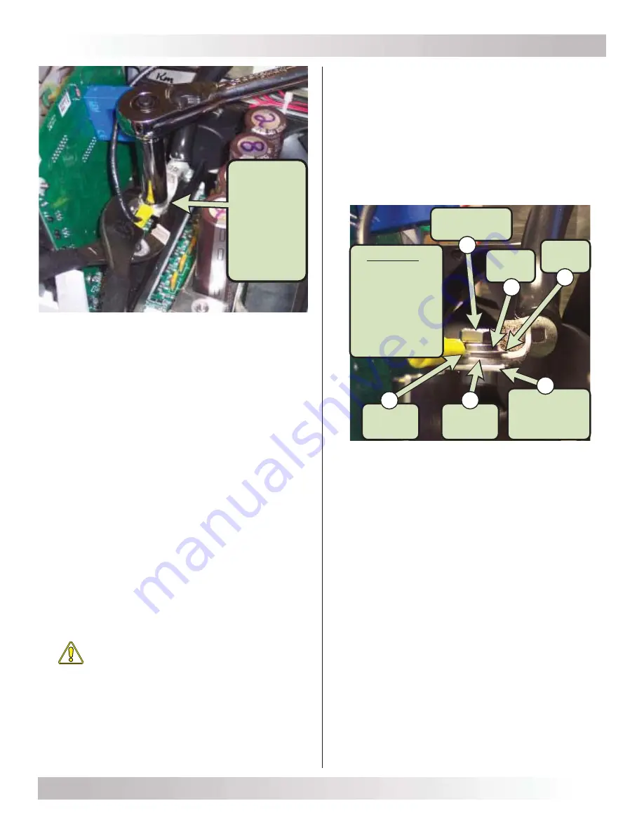
Figure 5, Connections to Busbar
5. Secure the new control board into the bottom 16-pin
FET board connector by screwing in the two #6-32
screws (T15 head) to the FET board. See Figure 3,
Item B.
6. The new control board is now installed. Review all the
connections a
fi
nal time to ensure they are correct.
7. If there are no other internal components to replace,
reinstall the top cover as described in the
Top Cover
Removal and Replacement with Internal Component
Identifi cation, Service Instructions: 64-1001
.
Use pliers to
hold the
busbar
while
removing or
replacing
the
¼-20 bolt
Sequence
1. ¼-20 bolt
2. Lock washer
3. Flat washer
4. Sense wire
5. Bus cable
6. Busbar
(captive nut)
¼-20 bolt
(7/16" head)
Busbar
(with captive
nut)
Bus
cable
Flat
washer
Lock
washer
Sense
wire
6
5
4
3
2
1


