background image

4

© 2018 Sensata Technologies

 Control Board Removal and Replacement

5.0 

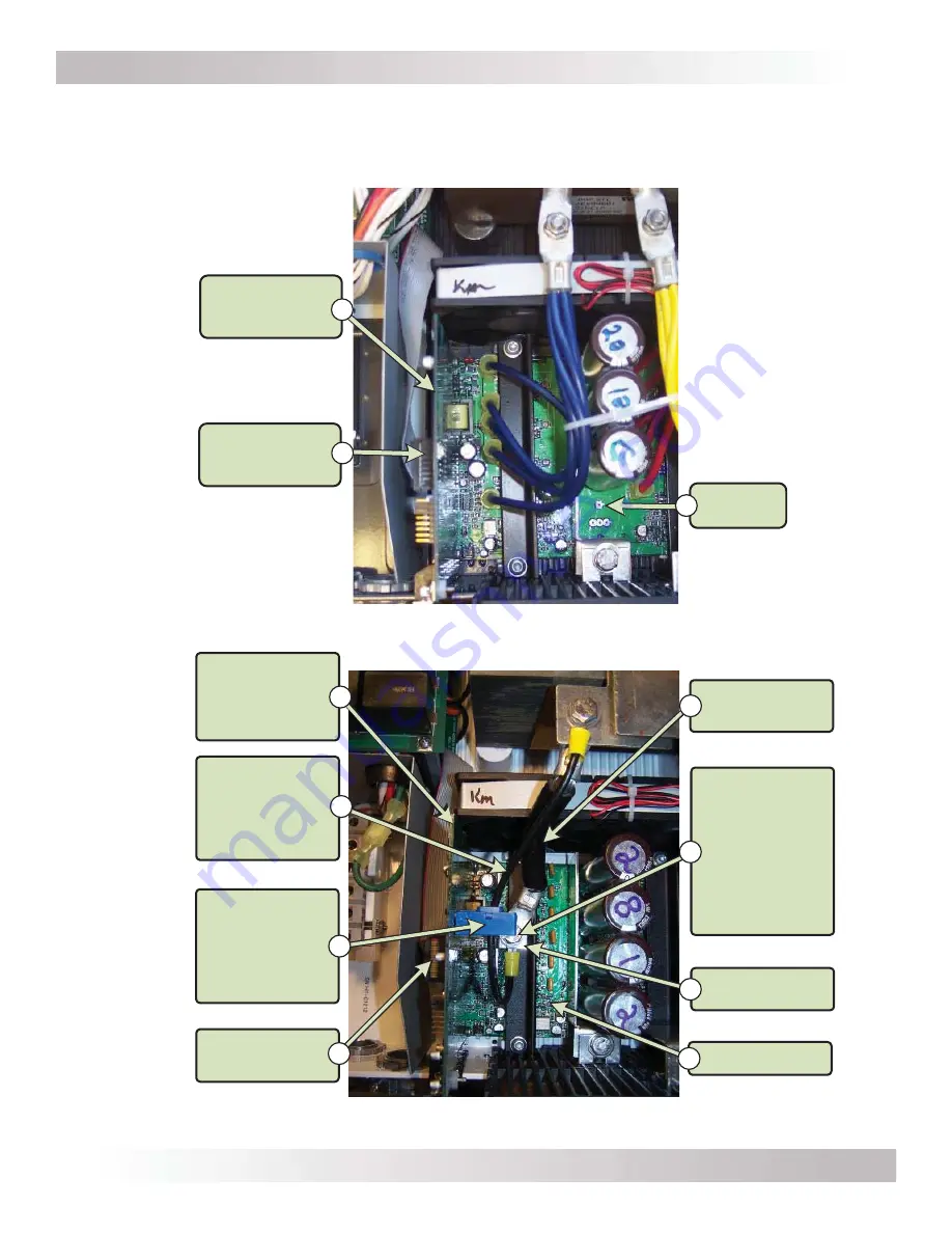
Identifying Components in the Control Board Compartment

Although Sensata offers multiple Magnum Energy inverter models—and uses a slightly different control board for each 

model—the location of the control board for each inverter series is identical. Familiarize yourself with the components 

involved in the removal and replacement of a control board.

Figure 6, ME/RD Series Control Board Compartment

16-pin Ribbon 

Cable Connector

B

ME/RD Series 

Control Board

A

FET Board

C

Figure 7, MS/MS-PAE Series Control Board Compartment

Negative

Bus Cable

Negative FET

Busbar

FET Board

¼-20 bolt 

(7/16" head) – 

holds Negative 

Bus Cable and 
Current Sense 

Wire to 

Negative FET 

Busbar

G

E

H

16-pin Ribbon

Cable Connector

LEM - current 

transducer

 (connected to 

MS/MS-PAE 

control board)

 Current

Sense Wire

(1 or 2 wires, 
depending on 

model)

MS/MS-PAE 

Series 

Control Board

(LEM type)

A

B

C

D

F

Summary of Contents for Magnum Energy ME-PAE Series

Page 1: ...tions when working with the control and FET boards and within the inverter Failure to follow ESD safety precautions could result in damage to internal components and the inverter 2 2 Included Materials Before dismantling the inverter inspect the new control board to ensure there is no obvious physical damage Look at the Model ID label on the new control board see Figure 1 or 2 Item A and verify th...

Page 2: ...e the two 6 32 screws T15 head securing the control board See Figure 3 Item B 4 Firmly pull up on the control board by its top edge or upper corners to remove it from the bottom 16 pin connector on the FET board The current sense wire Figure 7 Item B will still be attached through the LEM on the back 5 Look on the front of the control board and pull on the 16 pin ribbon connector to remove See Fig...

Page 3: ...ng the 20 bolt This connection must be torqued to 130 in lbs Use a pair of pliers to hold the negative FET busbar in place while this bolt is being tightened to prevent the busbar from twisting or breaking See Figure 4 for reference Caution Ensure the 20 bolt is reconnected in the same way as it was removed and is correctly torqued This connection carries very high DC current and an improper conne...

Page 4: ...volved in the removal and replacement of a control board Figure 6 ME RD Series Control Board Compartment 16 pin Ribbon Cable Connector B ME RD Series Control Board A FET Board C Figure 7 MS MS PAE Series Control Board Compartment Negative Bus Cable Negative FET Busbar FET Board 20 bolt 7 16 head holds Negative Bus Cable and Current Sense Wire to Negative FET Busbar G E H 16 pin Ribbon Cable Connec...

Reviews: