CamCor CT and PRO Series Hardware Manual
101
Section 8
ANALOG OUTPUT FUNCTION
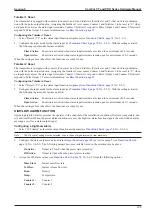
The transmitter is equipped with two analog outputs that can be assigned to mass flow, volume flow, temperature, density
and drive output.
Configuring an Analog Output
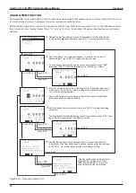
Use the following procedure to configure the parameters for your application:
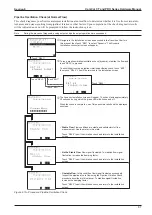
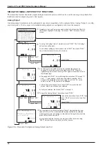
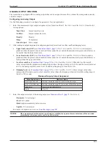
1. Select the measurement type (output assignment) (see Transition Chart 3, No. 2-4-1-1 and No. 2-4-2-1) from the fol
-
lowing options:
–
Mass Flow:
Instant mass flow rate
–
Vol Flow:
Instant volume flow rate
–
Density:
Density
–
Temp:
Temperature
–
Drive Output:
Drive output
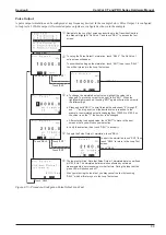
2. After making an output assignment, reconfigure upper limit, lower limit, low-flow cutoff and damping factor:
a.
Upper limit value (URV)
, No. 2-4-1-2 and No. 2-4-2-2):
A 4-mA output is
produced when the preset value is reached. Values cannot be set outside the maximum range (see table below) or
be smaller than the lower limit value.
b.
Lower limit value (LRV)
, No. 2-4-1-3 and No. 2-4-2-3): A 20-mA output is
produced when the preset value is reached. Values cannot be set outside the maximum range (see table below) or
be larger than the upper limit value.
c.
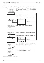
Low-flow cutoff
(see
, No. 2-4-1-4 and No. 2-4-2-4): When the low-flow cutoff
value is larger than the proportion of analog output (where the upper limit is set to 100% and the lower limit is set
to 0%), the analog output becomes 4 mA. Available setting range is from 0% to 10%.
d.
Damping factor
(see
, No. 2-4-1-5 and No. 2-4-2-5): Select a larger value when
analog output fluctuates greatly; select a smaller value when a fast response is desired. Available setting range is
from 0 to 200 seconds.
Maximum Range by Output Assignment
Output Assignment
Maximum Range
Instant mass flow rate
Maximum allowable range to maximum allowable range
Instant volume flow rate
Maximum allowable range/0.3 to maximum allowable range/0.3
Temperature
Sensor maximum temperature
Density
0.0 to 0.5
3.
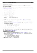
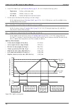
Select the output error state of the analog output (see
–
Downscale:
2.4 mA output
–
Zero:
4 mA output
–
Hold:
Output immediately before an error
–
Upscale:
21.6 mA output
For details of outputs in an error, see
CAUTION
When measurement-related unit set up at Assign is modified, the upper and lower limit values will be converted
automatically to the measures to read in the unit selected.
Summary of Contents for CamCor CC001
Page 14: ...14 CamCor CT and PRO Series Hardware Manual Section 3 This page is left blank intentionally ...
Page 24: ...24 CamCor CT and PRO Series Hardware Manual Section 3 This page is left blank intentionally ...
Page 54: ...54 CamCor CT and PRO Series Hardware Manual Section 5 This page is left blank intentionally ...
Page 62: ...62 CamCor CT and PRO Series Hardware Manual Section 7 This page is left blank intentionally ...

