A-2
CamCor CT and PRO Series Hardware Manual
Appendix A
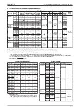
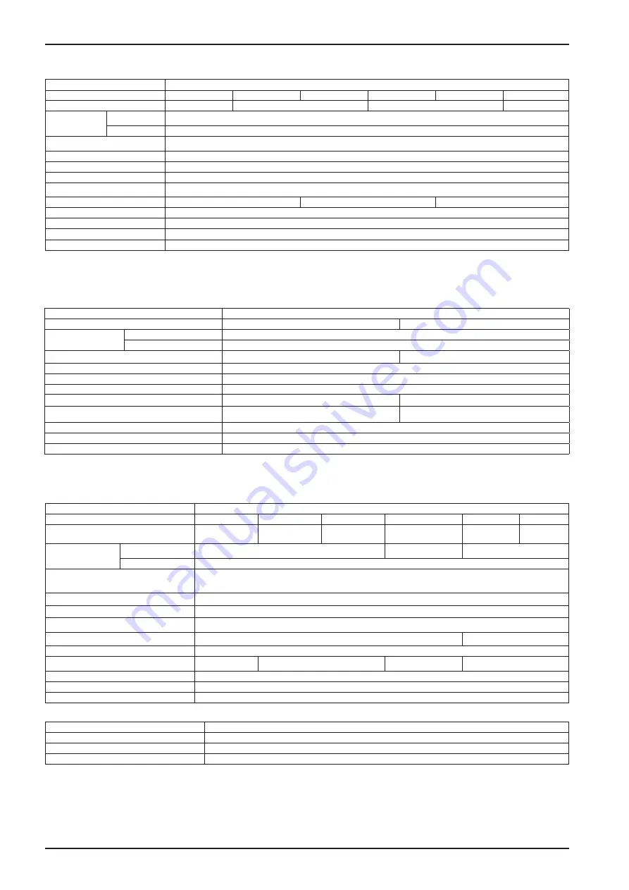
High-Flow Models (CC100 through CC250)
Item
Description
Model
CC100
CC150
CC15H
CC200
CC20H
CC250
Nominal size
100 mm, 4″, DN100
150 mm, 6″, DN150
200 mm, 8″, DN200
250 mm, 10″, DN250
Materials
Wetted parts
SUS316L
Housing
SUS304
Process connection
ASME 150, 300, 600 RF; DIN PN 10, 16, 25, 40 RF
Applicable fluids
Liquid
Density range
0.3 to 2.0 g/mL
Viscosity range
Maximum 10000 mPa·s
Temperature range
–200°C to 200°C
Tube withstand @ 37
.
8˚C
13.3 MPa
10.7 MPa
9.0 MPa
Maximum operating pressure
Dependent on flange rating
Flow direction
Bi-directional
Explosion-proof configuration
CSA, ATEX, and IECEx (Refer to
Section 10—Explosion-proof Specifications, page 113
Dust-tight, waterproof configuration
IP66/67
1. When SUS316L is selected as the wetted parts material, the flange material will be dual-rated SUS316/SUS316L.
2. ASME flanged process connections for Models CC20H and CC250 are limited to ASME classes 150 and 300.
3. Refer to
Section 10—Explosion-proof Specifications, page 113
for details. In case of non-explosion-proof type, the maximum measurement temperature is 130
°
C.
However, the product must be used within the maximum ambient temperature of 45
°
C. Higher temperature limits can be achieved with the high-temperature models.
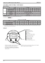
High-Pressure Models (CC010 and CC015)
Item
Description
Model
CC010
CC015
Materials
Wetted parts
Flow tube: Alloy C22; Manifold: Alloy C22 equivalent (CX2MW)
Housing
SUS304
Process connection
3/8-18 FNPT
3/4-14 FNPT
Applicable fluid
Liquid and gas
Density range
0.3 to 2.0 g/mL
Temperature range
Integrally-mounted: –20
°
C to 90
°
C; Separately-mounted: –200
°
C to 200
°
C
Maximum operating pressure @ 20
°
C
36 MPa
43 MPa
Sensor housing withstand
3.0 MPa
2.2 MPa
Flow direction
Bidirectional
Explosion-proof configuration
CSA, ATEX, and IECEx (Refer to
Section 10—Explosion-proof Specifications, page 113
for details.)
Dust-tight, waterproof configuration
IP66/67
1. This pressure does not represent the rated test pressure of a pressure vessel, but 1/4 of the factory-tested breakdown pressure or the data obtained from FEA analysis,
whichever is lower. Distorted enclosures do not constitute a failure of the test.
* For products conforming to the high-pressure gas safety regulations and CE marking, consult Cameron.
High-Temperature Models (CC025 to CC150)
Item
Description
Model
CC025
CC040
CC050
CC080
CC100
CC150
Nominal size
25 mm, 1˝,
DN25
40mm, 1-1/2˝,
DN40
50 mm, 2˝,
DN50
80 mm, 3˝,
DN80
100 mm, 4˝,
DN100
150 mm, 6˝,
DN150
Materials
Wetted parts
SUS316L
SUS316L, Alloy C22
SUS316L
Housing
SUS304
Process connection
1" to 3": ASME 150, 300, 600, 900
RF; DIN PN 10, 16, 25, 40 RF
4" and 6": ASME 150, 300, 600 RF; DIN PN10, 16, 25, 40 RF
Applicable fluids
Liquid
Density range
0.3 to 2.0 g/mL
Temperature range
–40
°
C to 350
°
C
Tube withstand @ 37.8˚C
10.5 MPa
13.3 MPa
Maximum operating pressure
Dependent on flange rating
Sensor housing withstand
1.6 MPa
1.8 MPa
1.4 MPa
—
Flow direction
Bi-directional
Explosion-proof configuration
CSA, ATEX, and IECEx (Refer to
Section 10—Explosion-proof Specifications, page 113
Dust-tight, waterproof configuration
IP66/67
Optional Heat Tracer Specifications (Available for Models CC025 through CC080)
Applicable fluids
Hot water, saturated steam, overheated steam
Heat retention fluid maximum output pressure
0.98 MPa
Joint port for heat retention fluid
10 mm stainless tubing
Recommended joint
Standard stainless steel ferrule-type compression fitting for 10mm tubing
1. When SUS316L is selected as the wetted parts material, the flange material will be dual-rated SUS316/SUS316L.
2. ASME 900 flanges are only available in Alloy C22 material.
3. Allowable ambient temperature permitted for the sensor unit is up to 50
°
C.
4. This pressure does not represent the rated test pressure of a pressure vessel, but 1/4 of the factory-tested breakdown pressure or the data obtained from FEA analysis,
whichever is lower. Distorted enclosures do not constitute a failure of the test.
5. Heat trace should only be used for heating the meter. Do not use for cooling of flowing media.
* For products conforming to the high-pressure gas safety regulations, consult Cameron.
* Only available with separately-mounted transmitter and interconnect cable (ordered separately; 10-meter minimum, available in 5-meter increments thereafter).
Summary of Contents for CamCor CC001
Page 14: ...14 CamCor CT and PRO Series Hardware Manual Section 3 This page is left blank intentionally ...
Page 24: ...24 CamCor CT and PRO Series Hardware Manual Section 3 This page is left blank intentionally ...
Page 54: ...54 CamCor CT and PRO Series Hardware Manual Section 5 This page is left blank intentionally ...
Page 62: ...62 CamCor CT and PRO Series Hardware Manual Section 7 This page is left blank intentionally ...


