B-4
CamCor CT and PRO Series Hardware Manual
Appendix B
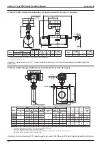
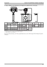
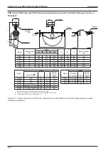
CT Series CC100 through CC250 Sensor with Integral Transmitter (Flanged)
134
230
64 127
60
A
H
h1
h2
W
15
L
Flow direction
Ground screw
Flange
Conduit connection
3/4-14 FNPT
(M25)
H
h1
h2
W
15
L
Flow direction
Ground screw
Ground screw
Flange
Conduit connection
3/4-14 FNPT
(M25)
Boss
1/4-18
FNPT
Boss
1/4-18
FNPT
Conduit connections
are 3/4-14 FNPT for
CSA units and M25
for ATEX units.
CC100, CC150
CC15H through CC250
Model
Flange
L
(mm)
H
(mm)
h1
(mm)
h2
(mm)
A
(mm)
W
(mm)
Approx.
Weight (kg)
Nominal size Flange rating
CC100
4"
ASME 150
1018
1403
1015
660
300
810
231
ASME 300
1036
ASME 600
1082
DN100
PN 10, 16
968
PN 25, 40
994
CC150
6"
ASME 150
1318
1403
1015
660
300
810
246
ASME 300
1338
ASME 600
1388
DN150
PN 10, 16
1250
PN 25, 40
1290
CC15H
6"
ASME 150
1087
1604
1190
851
320
810
310
ASME 300
1107
ASME 600
1157
DN150
PN 10, 16
1019
PN 25, 40
1059
CC200
8"
ASME 150
1418
1604
1190
851
320
810
340
ASME 300
1438
ASME 600
1494
DN200
PN 10, 16
1338
PN 25
1374
PN 40
1390
CC20H
8"
ASME 150
1418
1830
1390
960
420
1110
610
ASME 300
1438
DN200
PN 10, 16
1338
PN 25
1374
PN 40
1390
CC250
10"
ASME 150
1773
1830
1390
960
420
1110
650
ASME 300
1805
DN250
PN 10
1705
PN 16
1709
PN 25
1745
PN 40
1779
Figure B.6—Outline dimensions of CT Series flanged sensor units CC100 through CC250 with integral transmitter
(millimeters)
Summary of Contents for CamCor CC001
Page 14: ...14 CamCor CT and PRO Series Hardware Manual Section 3 This page is left blank intentionally ...
Page 24: ...24 CamCor CT and PRO Series Hardware Manual Section 3 This page is left blank intentionally ...
Page 54: ...54 CamCor CT and PRO Series Hardware Manual Section 5 This page is left blank intentionally ...
Page 62: ...62 CamCor CT and PRO Series Hardware Manual Section 7 This page is left blank intentionally ...

