15
Section 3
CamCor CT and PRO Series Hardware Manual
Section 3—Specifications and Performance (U.S. Customary
Units)
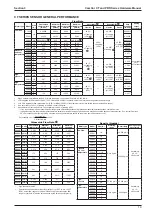
Specifications (Metric Units), page
.
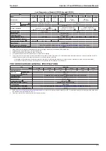
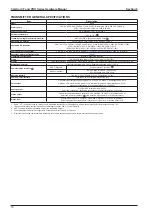
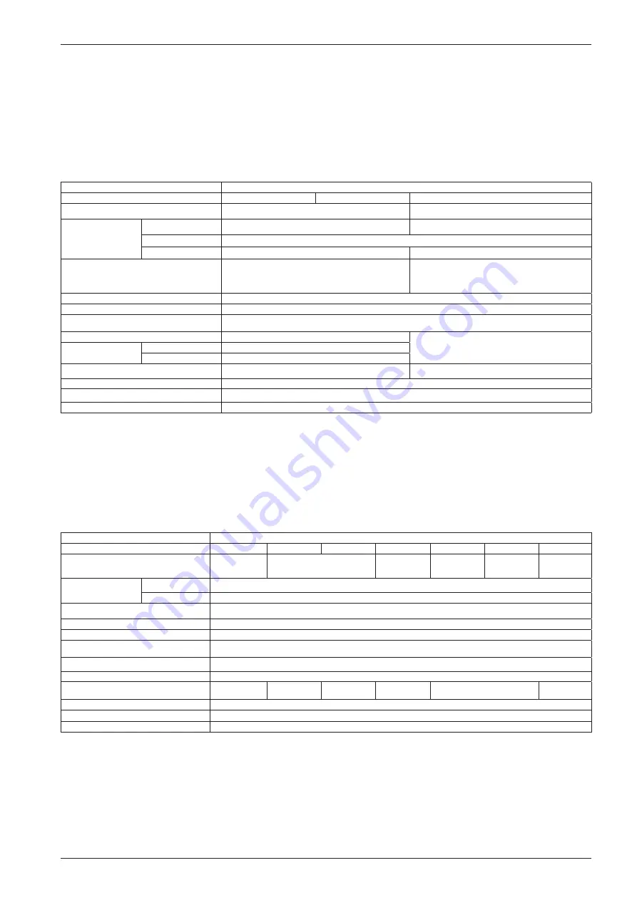
CT SERIES SENSOR GENERAL SPECIFICATIONS
Low-Flow Models (CC00A, CC001 and CC003)
Item
Description
Model
CC00A
CC001
CC003
Nominal size
1/4"
10 mm, 1/2″, DN15
Materials
Wetted parts
SUS316L
SUS316L, Alloy C22
Housing
SUS304
O-rings
Fluoro-elastomer (standard Viton®), PTFE (option)
—
Process connection
1/4-18 FNPT
ASME 100, 300, 600, 900
RF;
DIN PN 10, 16, 25, 40 RF
,
IDF Ferrule
, Threaded
Applicable fluid
Liquid and gas
Density range
0 to 2.0 g/mL
Temperature range
−328
°
F to 392
°
F
Tube withstand @ 100
°
F
—
Wetted parts materials: SUS316L maximum 1440 psig;
Alloy C22 maximum 2185 psig
(depending on flange rating)
Maximum operating
pressure @ 100
°
F
Liquid
2176 psi
Gas
142 psig
Sensor housing withstand
—
1044 psig
Flow direction
Bi-directional
Explosion-proof configuration
CSA, ATEX, and IECEx (Refer to
Section 10—Explosion-proof Specifications, page 113
Dust-tight, waterproof configuration
IP66/67
1. When SUS316L is selected as the wetted parts material, the flange material will be dual-rated SUS316/SUS316L.
2. ASME 900 flanges are only available in Alloy C22 material.
3. DIN flanges are only available for meter material SUS316L.
4. For application with foods, this product does not comply with CE marking.
5. This pressure does not represent the rated test pressure of a pressure vessel. It represents 1/4 of the factory-tested breakdown pressure or the data obtained from FEA
analysis, whichever is lower. Distorted enclosures do not constitute a failure of the test.
6. Refer to “Explosion-proof Specifications” on page 11 for details. In case of non-explosion-proof type, the maximum measurement temperature is 266°F. However, the
product must be used within the maximum ambient temperature of 113°F. Higher temperature limits can be achieved with the high-temperature models.
* Only available with separately-mounted transmitter and interconnect cable (ordered separately;10-meter minimum, available in 5-meter increments thereafter).
* For products conforming to the high-pressure gas safety regulations and CE marking, consult Cameron.
Standard Models (CC006 through CC080)
Item
Description
Model
CC006
CC010
CC015
CC025
CC040
CC050
CC080
Nominal size
10 mm, 1/2",
DN15
15 mm, 1/2˝,
DN15
25 mm, 1˝,
DN25
40 mm, 1-1/2˝,
DN40
50 mm, 2˝,
DN50
80 mm, 3˝,
DN80
Materials
Wetted parts
SUS316L, Alloy C22
Housing
SUS304
Process connection
ASME 150, 300, 600, 900
RF; DIN PN 10, 16, 25, 40 RF
; IDF Ferrule
; Threaded
Applicable fluids
Liquid and gas
Density range
0 to 2.0 g/mL
Temperature range
−328°F to 392°F
Tube withstand @ 100
°
F
SUS316L: 1520 psig; Alloy C22: 2276 psig
Maximum operating pressure
Depends on flange rating
Sensor housing withstand
551 psig
435 psig
319 psig
232 psig
261 psig
203 psig
Flow direction
Bi-directional
Explosion-proof configuration
CSA, ATEX, and IECEx (Refer to
Section 10—Explosion-proof Specifications, page 113
Dust-tight, waterproof configuration
IP66/67
1. When SUS316L is selected as the wetted parts material, the flange material will be dual-rated SUS316/SUS316L.
2. ASME 900 flanges are only available in Alloy C22 material.
3. DIN flanges are only available for meter material SUS316L.
4. For application with foods, this product does not comply with CE marking.
5. This pressure does not represent the rated test pressure of a pressure vessel. It represents 1/4 of the factory-tested breakdown pressure or the data obtained from FEA
analysis, whichever is lower. Distorted enclosures do not constitute a failure of the test.
6. Refer to
Section 10—Explosion-proof Specifications, page 113
for details. In case of non-explosion-proof type, the maximum measurement temperature is 266
°
F. Howev-
er, the product must be used within the maximum ambient temperature of 113
°
F. Higher temperature limits can be achieved with the high-temperature models.
* Available with either integrally-mounted or separately-mounted transmitter.
* For products conforming to the high-pressure gas safety regulations and CE marking, consult Cameron.
Summary of Contents for CamCor CC001
Page 14: ...14 CamCor CT and PRO Series Hardware Manual Section 3 This page is left blank intentionally ...
Page 24: ...24 CamCor CT and PRO Series Hardware Manual Section 3 This page is left blank intentionally ...
Page 54: ...54 CamCor CT and PRO Series Hardware Manual Section 5 This page is left blank intentionally ...
Page 62: ...62 CamCor CT and PRO Series Hardware Manual Section 7 This page is left blank intentionally ...


